 |
|||
|
|
|||
|
|
|||
| ||||||||||
|
|
 TM 9-2350-238-20-1
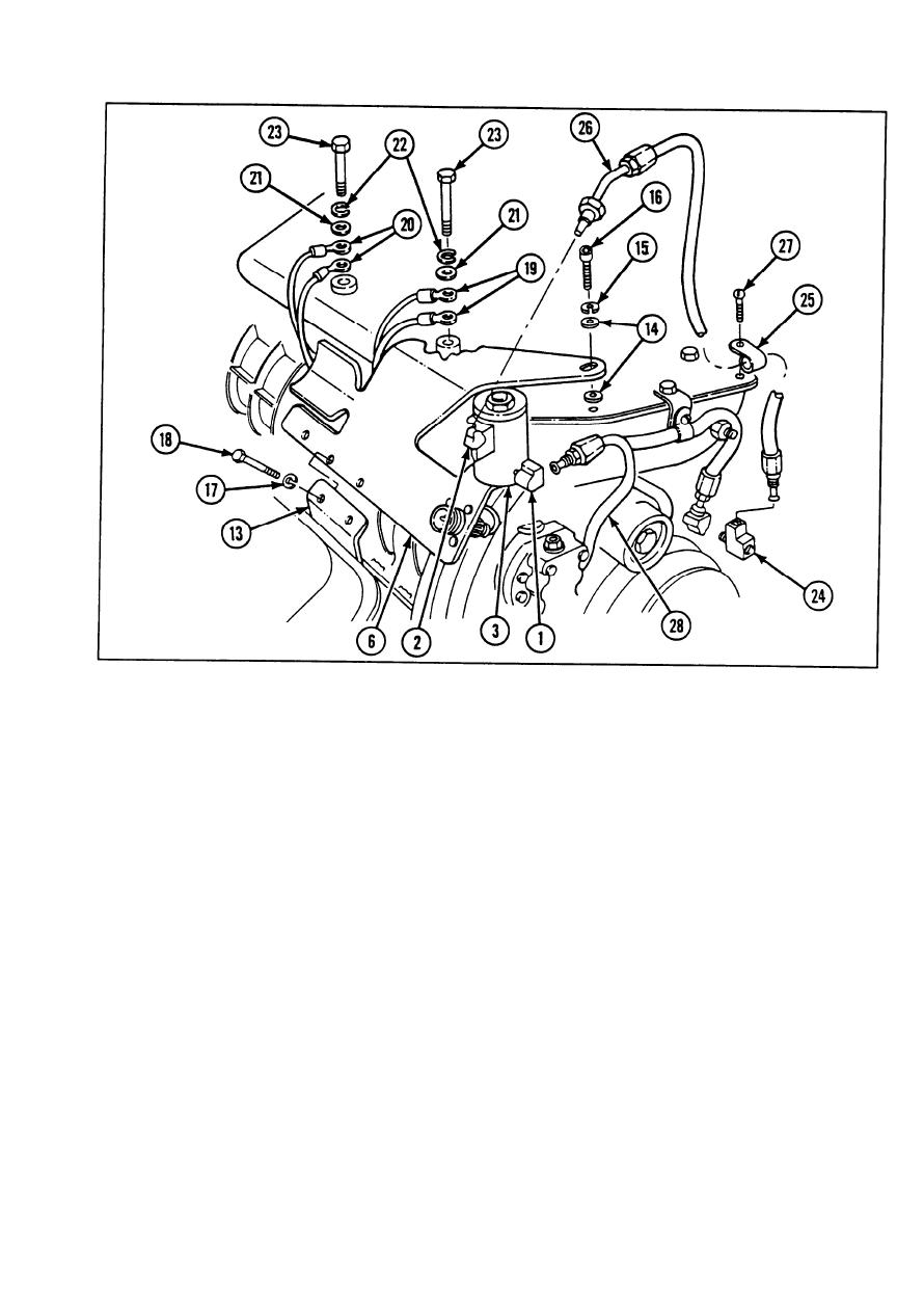
6 Position angle bracket (6) on governor housing and inboard of fuel pump support (13). Route
wiring harness to prevent cuts, chafing, burns, and interference with components. Loosely
secure angle bracket to governor housing with four flat washers (14), two new Iockwashers (15),
and two machine screws (16).
7 Secure angle bracket (6) to fuel pump support (13) with two new Iockwashers (17) and two
hexagon head capscrews (18). Torque hexagon head capscrews to 30 to 35 ft-lb (41 to 47 N-
m). Tighten two machine screws (16).
8 Secure wiring harness leads (19 and 20) to air inlet housing with two flat washers (21), two new
Iockwashers (22), and two hexagon head capscrews (23). Torque hexagon head capscrews to
16 to 20 ft-lb (22 to 27 N-m).
9 Install tee (24) on left cylinder head.
10 If removed, install loop clamp (25) on fuel hose (26) and secure to governor cover using screw
assembly (27). Install fuel hose in tee (24).
2-493
|
|
Privacy Statement - Press Release - Copyright Information. - Contact Us |