 |
|||
|
|
|||
|
Page Title:
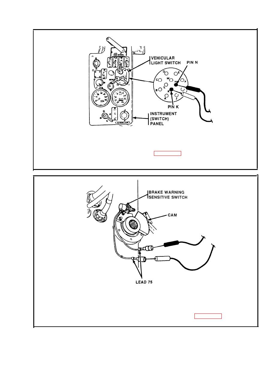
BLACKOUT STOPLIGHT CIRCUIT. (Cont) |
|
||
| ||||||||||
|
|
 TM 9-2350-238-20-1
Place red probe on pin K. Place black probe on pin N. If multimeter
Step 5.
indicates 0 ohms, go to step 6. If multimeter indicates infinity, replace
vehicular light switch. Refer to page 2-566. Connect connector to vehicular
light switch.
Disconnect both leads 75 from brake warning sensitive switch. Connect
Step 6.
multimeter to brake warning sensitive switch leads. Apply brakes. If
multimeter indicates 0 ohms, repair lead 75 between brake warning
sensitive switch and vehicular light switch. If multimeter indicates infinity,
replace brake warning sensitive switch. Refer to page 2-626. Connect
leads to brake warning sensitive switch.
2-253
|
|
Privacy Statement - Press Release - Copyright Information. - Contact Us |
