 |
|||
|
|
|||
|
Page Title:
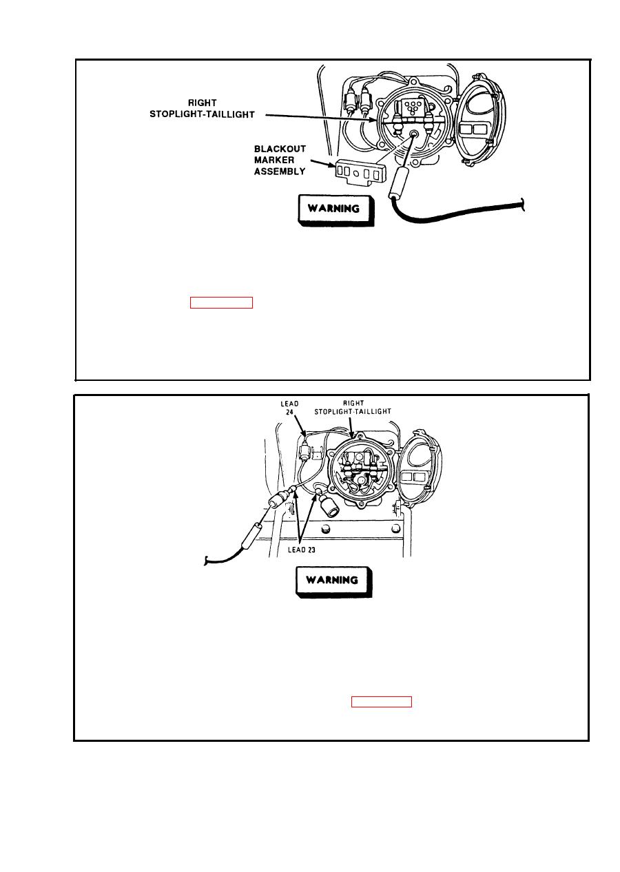
BLACKOUT STOPLIGHT CIRCUIT. (Cont) |
|
||
| ||||||||||
|
|
 TM 9-2350-238-20-1
Make sure MASTER switch is OFF before repairing electrical
circuits. Failure to observe this warning could result in injury to
personnel.
Remove blackout marker assembly from fight stoplight-taillight. Refer to
Step 1.
main light switch and place in blackout drive position. Place blackout-
infrared selection switch in blackout position. Place red probe in socket.
Ground black probe. If multimeter indicates about 24 volts, replace blackout
marker assembly. If multimeter indicates no voltage, set MASTER switch
OFF, install marker assembly and go to step 2.
Make sure MASTER switch is OFF before repairing electrical
circuits. Failure to observe this warning could result in injury to
personnel.
Disconnect lead 23 from right stoplight-taillight. Place red probe in lead 23.
Step 2.
Ground black probe. Set MASTER switch ON. Turn vehicular light switch
to BO STOP. Apply brakes. If multimeter indicates about 24 volts, repair
right stoplight-taillight. Refer to page 2-617. If multimeter indicates no
voltage, go to step 3. Set MASTER switch OFF. Turn vehicular light switch
OFF. Connect lead.
2-251
|
|
Privacy Statement - Press Release - Copyright Information. - Contact Us |
