 |
|||
|
|
|||
|
Page Title:
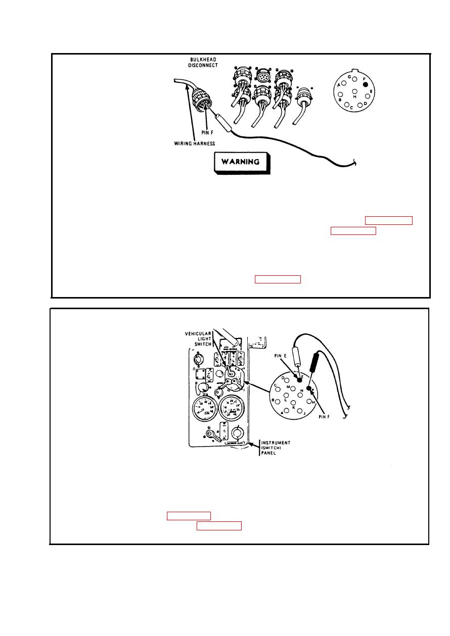
BLACKOUT MARKER CIRCUIT. (Cont) |
|
||
| ||||||||||
|
|
 TM 9-2350-238-20-1
Make sure MASTER switch is OFF before repairing electrical
circuits. Failure to observe this warning could result in injury to
personnel.
To access bulkhead disconnect, remove driver's seat, refer to page 2-952;
Step 5.
and remove driver's compartment aft cowl, refer to page 2-928. Disconnect
wiring harness at bulkhead disconnect. Place red probe on pin F (lead 24).
Ground black probe. Set MASTER switch ON. Turn vehicular light switch
to BO MARKER. If multimeter indicates about 24 volts, go to step 6. If
multimeter indicates no voltage, repair lead 24 between bulkhead discon-
nect and light switch. Refer to page 2-371. Set MASTER switch OFF.
Turn vehicular light switch OFF. Connect lead.
..
.
:
Step 6.
Disconnect connector from vehicular light switch. Place red probe on pin E
of vehicular light switch. Place black probe on pin F. Turn vehicular light
switch to BO MARKER. If multimeter indicates 0 ohms, repair lead 20&24.
Refer to page 2-371. If multimeter indicates infinity, replace vehicular light
switch. Refer to page 2-566. Connect connector to vehicular light switch.
Turn vehicular light switch OFF.
2-239
|
|
Privacy Statement - Press Release - Copyright Information. - Contact Us |
