 |
|||
|
|
|||
|
|
|||
| ||||||||||
|
|
 TM 9-2350-238-20-1
2-12. ELECTRICAL CIRCUIT TROUBLESHOOTING (CONT).
Make sure MASTER switch is OFF before repairing
electrical circuits. Failure to observe this warning
could result in injury to personnel.
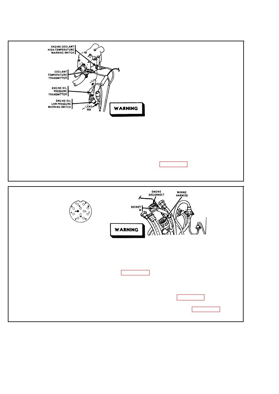
Step 3.
Disconnect lead 509 from engine oil low-pressure warning switch. Place
red probe in lead 509. Ground black probe. Set MASTER switch ON.
Set INST switch ON. If multimeter indicates about 24 volts, replace engine
oil low-pressure warning switch. Refer to page 2-626. If multimeter
indicates no voltage, go to step 4. Set MASTER switch OFF. Set INST
switch OFF.
Make sure MASTER switch is OFF before
repairing electrical circuits. Failure to observe
this warning could result in injury to personnel.
Step 4.
To access engine disconnect, remove hull transmission compartment
deck assembly. Refer to page 2-938. Disconnect wiring harness at
engine disconnect. Place red probe in plug socket N. Ground black
probe. Set MASTER switch ON. Set INST switch ON. If multimeter
indicates about 24 volts, repair lead 509 between engine disconnect and
engine oil low-pressure warning switch. Refer to page 2-371. If
multimeter indicates no voltage, repair lead 509 from engine disconnect to
driver's instrument (switch) panel disconnect. Refer to page 2-371. Set
MASTER switch OFF. Set INST switch OFF.
2-190
|
|
Privacy Statement - Press Release - Copyright Information. - Contact Us |
