 |
|||
|
|
|||
|
Page Title:
GENERATOR CHARGING CIRCUIT. (Cont) |
|
||
| ||||||||||
|
|
 TM 9-2350-238-20-1
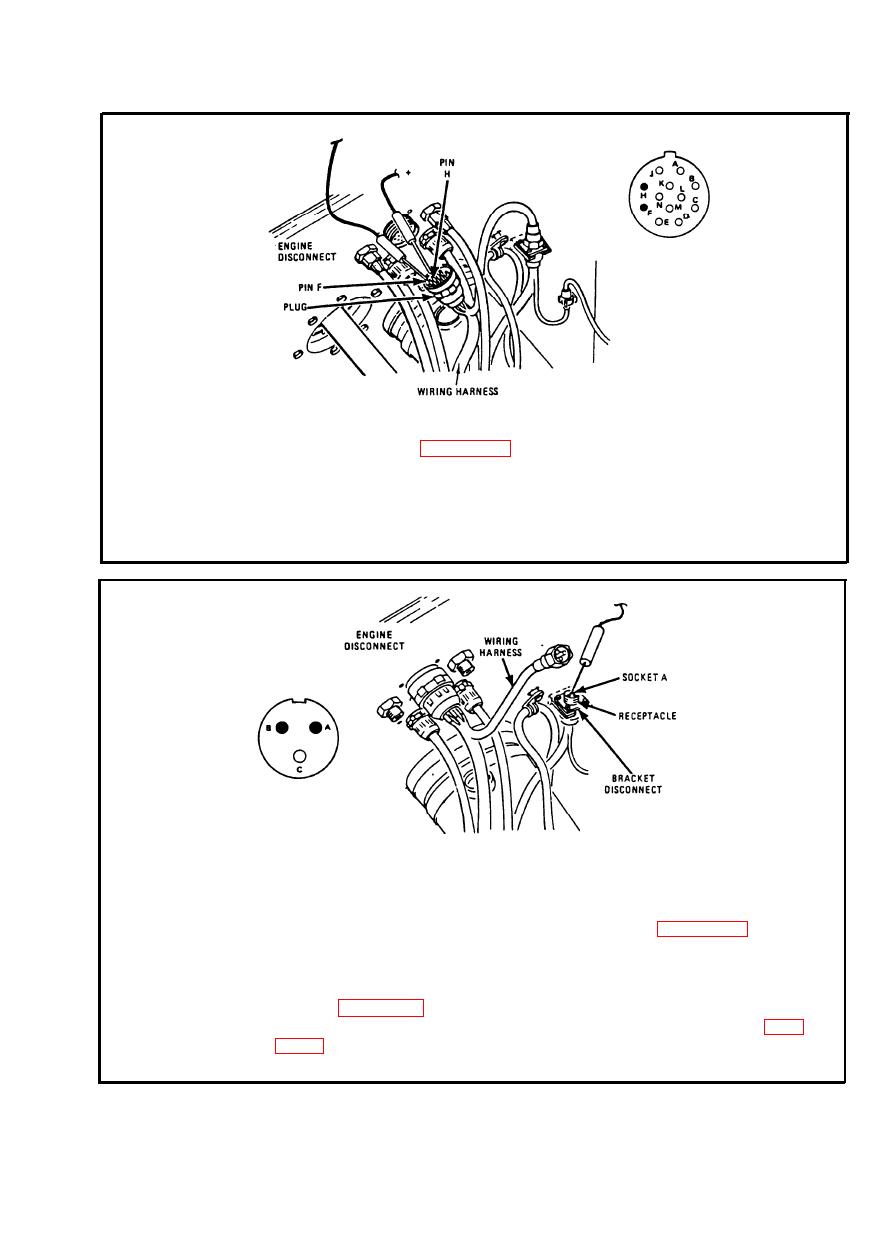
To access engine disconnect, remove hull transmission compartment deck
Step 9.
assembly. Refer to page 2-938. Disconnect wiring harness at engine
disconnect. Check resistance between plug pin F (lead 478) and ground.
Check resistance between plug pin H (lead 1) and ground. If multimeter
indicates 0 to 4 ohms on both pins, go to step 11. If multimeter indicates
more than 4 ohms on one or both pins, go to step 10. Connect wiring
harness at engine disconnect.
Step 10. Disconnect wiring harness at bracket disconnect (near engine disconnect).
Check resistance between receptacle socket A (lead 478) and ground.
Check resistance between receptacle socket B (lead 1) and ground. If
multimeter indicates 0 to 4 ohms on pin A, repair lead 478 between
bracket disconnect and engine disconnect. Refer to page 2-371. If
multimeter indicates 0 to 4 ohms on pin B, repair lead 1 between bracket
disconnect and engine disconnect. If multimeter indicates more than 4
ohms on pin A, repair lead 478 between bracket disconnect and generator.
Refer to page 2-371. If multimeter indicates more than 4 ohms on pin B,
repair lead 1 between bracket disconnect and generator. Refer to page
disconnect).
2-145
|
|
Privacy Statement - Press Release - Copyright Information. - Contact Us |
