 |
|||
|
|
|||
|
Page Title:
SECTION II. MANUFACTURING INSTRUCTIONS |
|
||
| ||||||||||
|
|
 TM 9-2330-202-14&P
Section II.
MANUFACTURING INSTRUCTIONS
Paragraph
Page
Number
Paragraph Title
Number
NOTE
Change 2 adds the M101A1. Specific M101A1 information is contained in this
chapter and designated in the chapter and section indexes.
Hydraulic Brake Tube Assembly, Front (M101A2 and M116A2) . . . . . . . . . . . . . . . . . . . . . . . .
Hydraulic Brake Tube Assembly, Front (M101A3, M116A2E1, and M116A3) . . . . . . . . . . . . . .
Hydraulic Brake Tube Assembly, Rear (M101A2 and M116A2) . . . . . . . . . . . . . . . . . . . . . . . . .
Hydraulic Brake Tube Assembly, Rear (M101A3, M116A2E1, and M116A3) . . . . . . . . . . . . . .
Hydraulic Brake Tube Assembly, Left and Right (M101A2, M116A2, and M116A2E1) . . . . . . .
Hydraulic Brake Tube Assembly, Left (M101A3 and M116A3). . . . . . . . . . . . . . . . . . . . . . . . . .
Hydraulic Brake Tube Assembly, Right (M101A3 and M116A3) . . . . . . . . . . . . . . . . . . . . . . . .
Drawbar Clamp Spacer (M101A2 and M116A2) . . . . . . . . . . . . . . . . . . . . . . . . . . . . . . . . . . . .
Adjustable Front Support Leg Chain . . . . . . . . . . . . . . . . . . . . . . . . . . . . . . . . . . . . . . . . . . . . .
1.
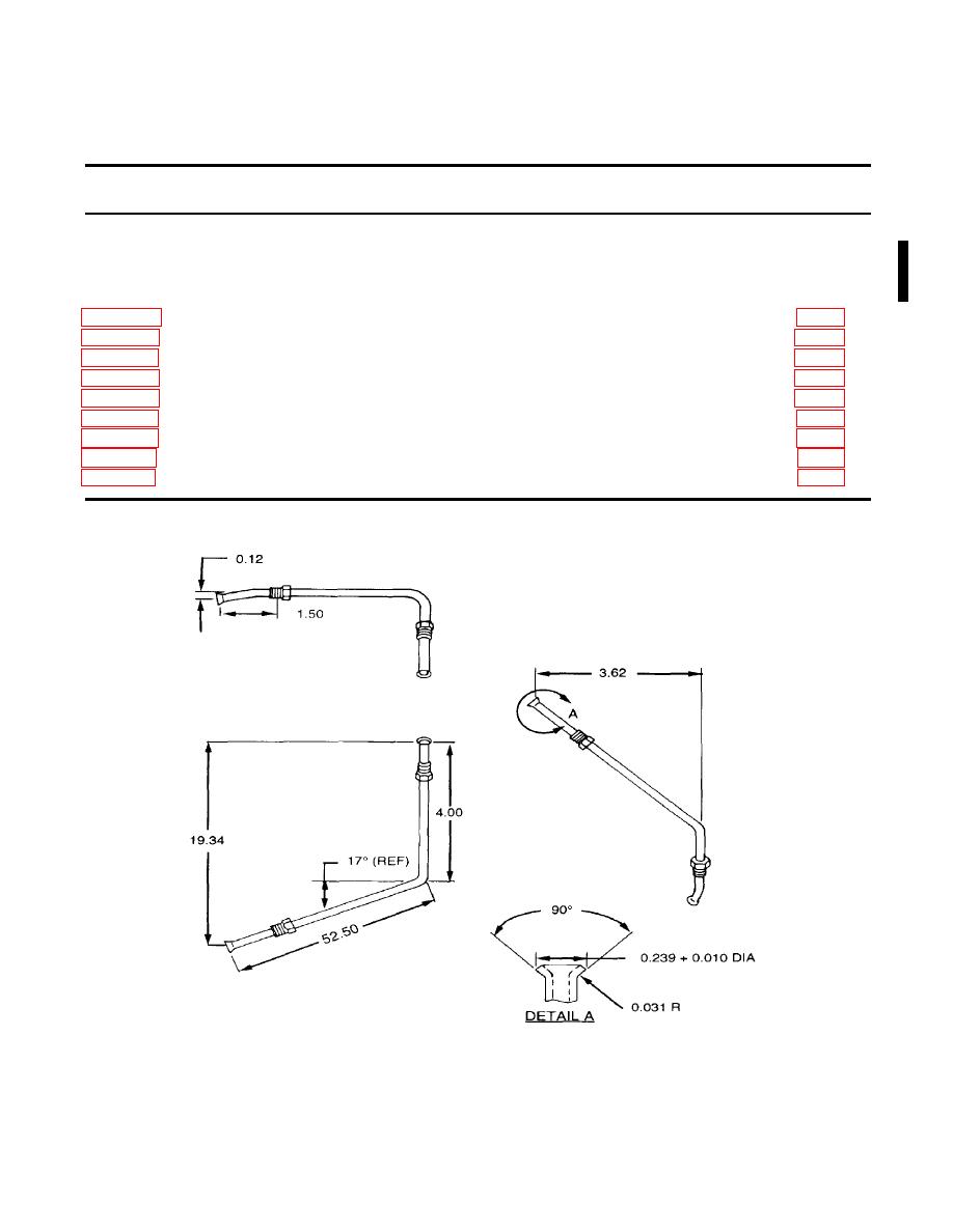
Fabricate from tube, part number 10943231, NSN 4710-00-102-0108.
2.
Cut to proper length and bend as shown to create part number 11686100-56.5.
3.
Install nut, part number 110357, on each end of tube assembly, as shown.
|
|
Privacy Statement - Press Release - Copyright Information. - Contact Us |