 |
|||
|
|
|||
|
|
|||
| ||||||||||
|
|
 TM 9-2330-202-14&P
4-38.
HYDRAULIC BRAKE ACTUATOR ASSEMBLY REPLACEMENT (continued).
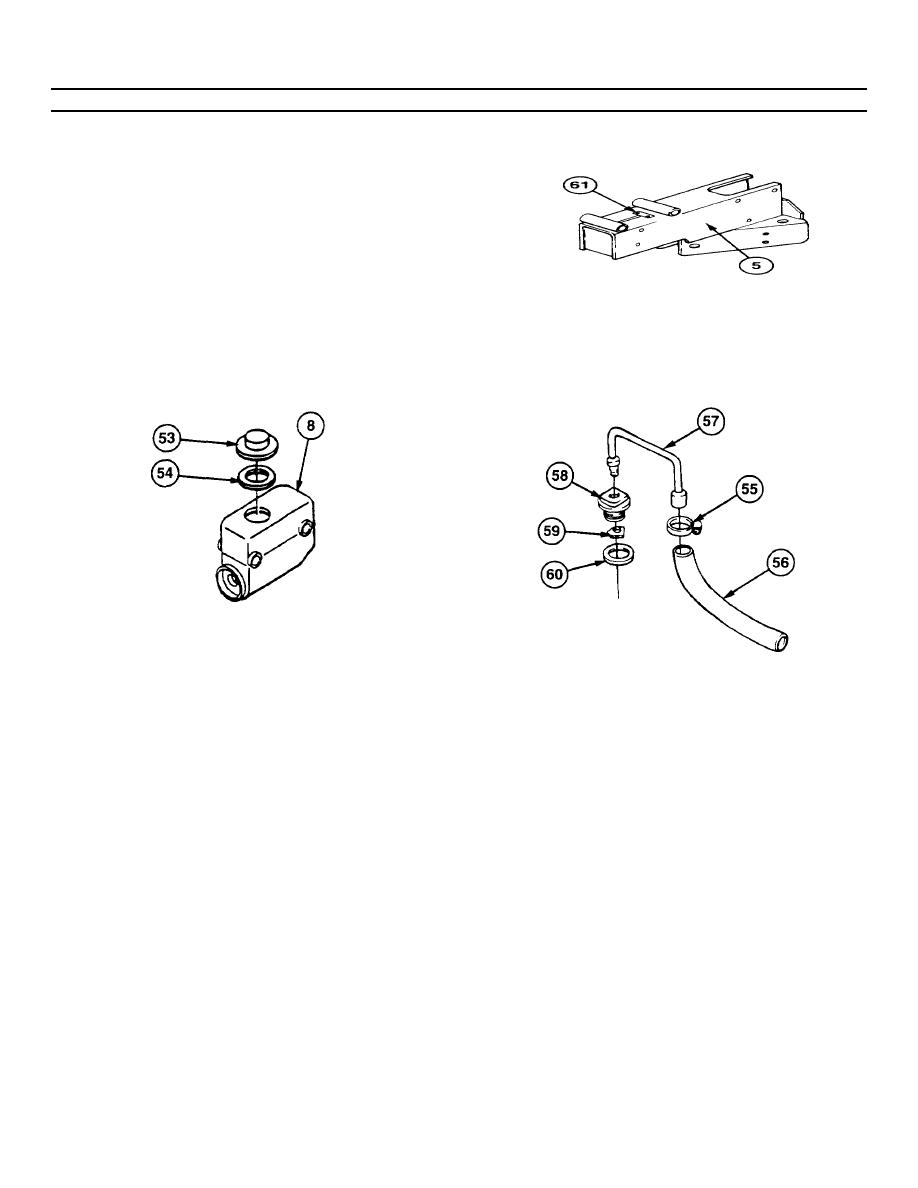
9.Inspect channel for broken leaf spring (61). If leaf spring (61) is damaged, replace hydraulic brake actuator assembly
(5).
d.
ASSEMBLY
NOTE
For trailers with master cylinder cap, do step 1.
For trailers with drain hose, do steps 2 and 3.
1.
Install gasket (54) and cap (53) on master cylinder (8) and finger-tighten.
2.
Install gasket (60), baffle (59), filler cap (58), and vent tube (57) on master cylinder (8).
3.
Install drain hose (56) on vent tube (57) and tighten clamp (55).
4.
If removed, install chain (52) on breakaway lever (51).
5.
Position breakaway lever (51) in channel (31) with ratchet teeth facing leaf spring (61). Install capscrew (50) and new
self-locking nut (49) on breakaway lever (51). Torque self-locking nut between 10 and 15 Ib-ft (14-20 Nm)
6.
If removed. attach boot (48) to rod end of pushrod (45). Assemble spring (47) and washer (46) on slot end of
pushrod (45). Install slot end of pushrod (45) on drawbar coupler (39) with socket head screw (44) and new self-
locking nut (43). Torque self-locking nut between 20 and 25 Ib-ft (27-34 Nm).
7.
Install piston rod end of shock absorber (42) on drawbar coupler (39) with capscrew (41) and new self-locking nut
(40). Torque self-locking nut between 20 and 25 Ib-ft (27-34 Nm).
8.
Install drawbar coupler (39) on channel (31) with eight bearings (38), four shafts (37) and links (36), and eight new
self-locking nuts (35). Torque self-locking nuts between 35 and 40 Ib-ft (47-54 Nm).
9.
Install other end of shock absorber (42) on channel (31) with capscrew (30) and new self-locking nut (29). Torque
self-locking nut between 20 and 25 Ib-ft (27-34 Nm).
4-68
|
|
Privacy Statement - Press Release - Copyright Information. - Contact Us |