 |
|||
|
|
|||
|
Page Title:
No. 2 and No. 3 Axle Bracket Removal |
|
||
| ||||||||||
|
|
 TM 9-2320-360-20-2
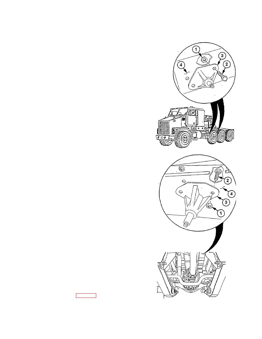
c. No. 2 and No. 3 Axle Bracket Removal
NOTE
Left and right sh ock absorber
brackets are replaced the same
way. Right side is shown.
No. 2 and no. 3 axle brackets are
mounted on outside of frame.
Remove two locknuts (1), screws (2), and
bracket (3) from frame (4). Discard locknuts.
d. No. 2 and No. 3 Axle Bracket Installation
Install bracket (3) on frame (4) with two screws
(2) and locknuts (1). Torque to 380 lb-ft (515
Nm).
e. No. 4 Axle Bracket Removal
NOTE
Left and right shock absorber
brackets are replaced the same
way. Left side is shown.
No. 4 axle bracket is mounted on
inside of frame.
Remove two locknuts (1), screws (2), and
bracket (3) from frame (4). Discard locknuts.
f. No. 4 Axle Bracket Installation
Install bracket (3) on frame (4) with two screws
(2) and new locknuts (1). Torque to 380 lb-ft
(515 Nm).
g. Follow-On Maintenance
Install shock absorbers (para 15-3).
15-17 (15-18 blank)
|
|
Privacy Statement - Press Release - Copyright Information. - Contact Us |