 |
|||
|
|
|||
|
|
|||
| ||||||||||
|
|
 TM 9-2320-360-20-2
NOTE
Locating hole in lever arm should line
up with corresponding hole in valve
mounting bracket.
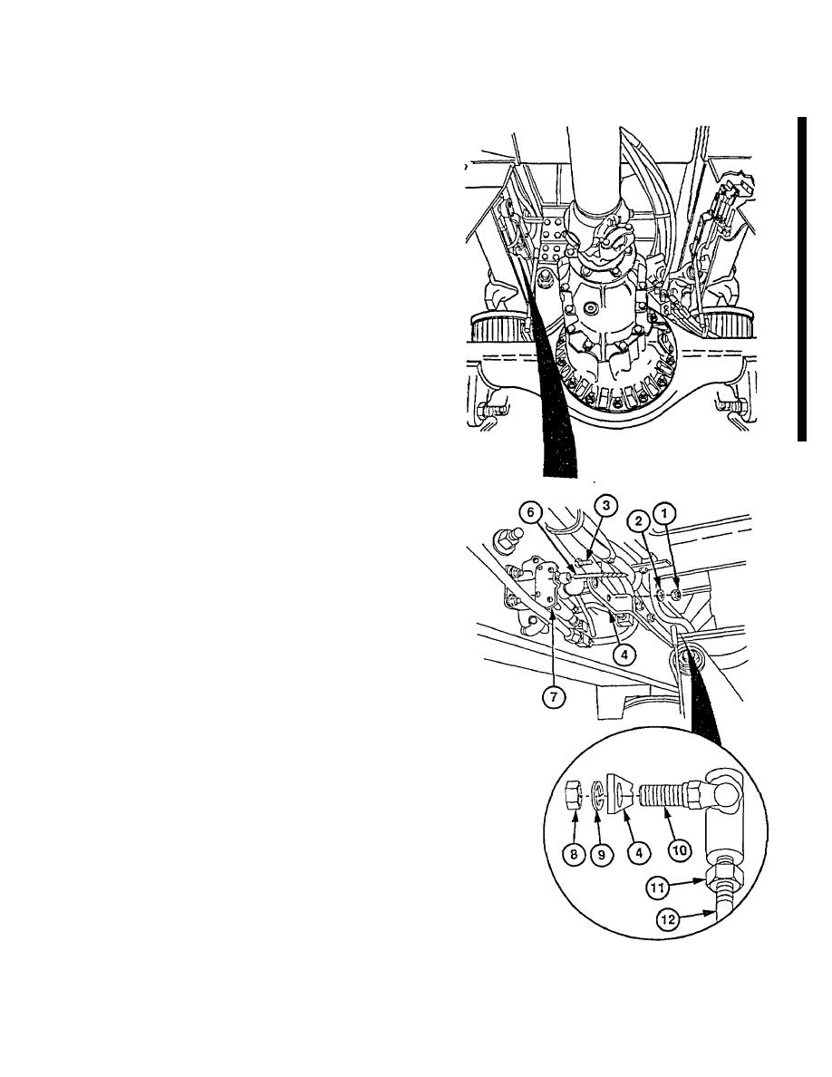
(3) Insert 3/16 in. twist drill (6) through locating
hole in valve lever arm (4) and
corresponding hole in mounting bracket (7).
CAUTION
Valve lever arm must be positioned
over pin on end of valve assembly.
NOTE
Do steps (5) thru (9) only if screw
cannot be installed in step (4).
(4) Install screw (3), washer (2), and new
locknut (1) on valve lever arm (4).
(5) Remove nut (8), lockwasher (9), an d
upper ball joint (10) from valve lever arm
(4). Discard lockwasher.
(6) Loosen two jamnuts (11) from ball joints
(10) on adjusting rod (12).
NOTE
Center rod between ball joints. Use
amount of thread visible on rod as a
guide.
(7) Turn rod (12) and upper ball joint (10)
clockwise
to
shorten
linkage
or
counterclockwise to lengthen linkage.
(8) Install upper ball joint (10) on valve lever
arm (4) with new lockwasher (9) and nut (8).
(9) Tighten two jamnuts (11) on adjusting rod (12).
CAUTION
Damage to height control valve and
linkage may occur if twist drill is not
removed
before
suspension
is
allowed to move.
(10) Remove 3/16 in. twist drill (6) from valve
lever arm (4).
(11) Remove wheel chocks and drive HET
Tractor several miles.
Recheck ride
height for 9 0.31 in. (23 0.8 cm).
(12) Repeat steps (1) thru (11) if necessary to
establish correct ride height.
b. Follow-On Maintenance
Remove wheel chocks.
15-11
|
|
Privacy Statement - Press Release - Copyright Information. - Contact Us |