 |
|||
|
|
|||
|
|
|||
| ||||||||||
|
|
 TM 9-2320-360-20-2
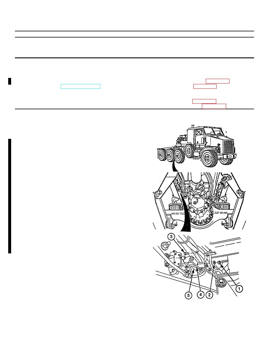
15-4. RIDE HEIGHT ADJUSTMENT
This task covers:
a. Adjustment
b. Follow-On Maintenance
INITIAL SETUP
Equipment Conditions
Tools and Special Tools
HET Tractor parked on hard, level surface.
Tool Kit, Genl Mech (Item 54, Appendix F)
Parking brake on (TM 9-2320-360-10).
Drill Set, Twist (Item 9, Appendix F)
Wheels chocked.
Air system pressurized to 120-125 psi
Materials/Parts
(827-862 kPa).
Locknuts (2) (Item 72, Appendix G)
Lockwashers (2) (Item 100, Appendix G)
a. Adjustment
NOTE
Due to characteristics of air
spring suspension, allow 5
minutes
for
suspension
to
stabilize
before
beginning
adjustment.
Do not attempt adjustment it
difference between bottom of
frame and ground is less than 1.5
in. (38.1 mm) from side to side.
Trailer must be disconnected
from HET Tractor when setting
ride height adjustment.
Air pressure must be at least 65
psi (450 kPa) for air ride system
to function.
Both ride height valves are
adjusted the same way. Right
valve is shown.
(1) Remove locknut (1), washer (2), and
screw (3) from valve lever arm (4).
Discard locknut.
NOTE
Correct ride height is 9 in. (23 cm)
measured from top of no. 3 axle to
bottom of frame rail.
(2) Push valve (5) up to raise or down to
lower ride height.
15-10
|
|
Privacy Statement - Press Release - Copyright Information. - Contact Us |