 |
|||
|
|
|||
|
|
|||
| ||||||||||
|
|
 TM 9-2320-360-20-2
11-4. SLACK ADJUSTER (MANUAL) REPLACEMENT (CONT)
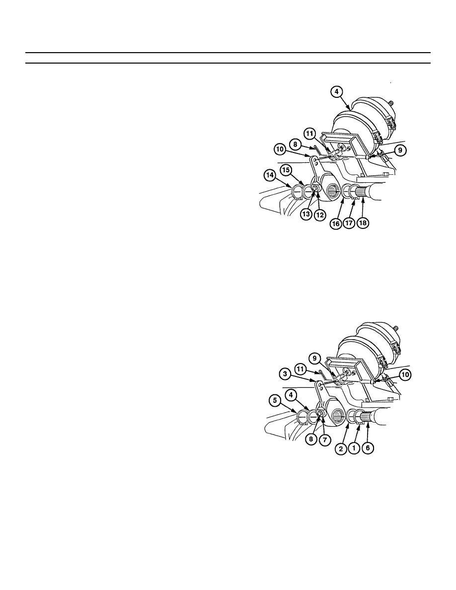
(8) Remove cotter pin (8), pin (9), and slack
adjuster (10) from clevis (11) of brake
chamber (4). Discard cotter pin.
(9) Push lock (12) in while turning adjusting
screw
(13)
counterclockwise
one
revolution.
WARNING
Wear eye protection and use care
when removing snap rings. Snap
rings are under spring tension and
can act as projectiles when released
and may cause severe eye Injury.
NOTE
Axles no. 2 and no. 3 do not have a
snap ring between axle housing and
washer.
(10) Remove snap ring (14), washer (15), slack
adjuster (10), washer (16), and snap ring
(17) from brake camshaft (18).
b. Installation
NOTE
Install slack adjuster so that
adjusting nut faces away from
brake chamber.
Axles no. 2 and no. 3 do not
have a snap ring between axle
housing and washer.
(1) Install snap ring (1), washer (2), slack
adjuster (3), washer (4), and snap ring (5)
on brake camshaft (6).
(2) Push lock (7) in while turning adjusting
screw (8) clockwise until holes in clevis (9)
and slack adjuster (3) are aligned.
(3) Install pin (10) through clevis (9) and slack
adjuster (3).
(4) Install new cotter pin (11) in pin (10).
11-10 Change 3
|
|
Privacy Statement - Press Release - Copyright Information. - Contact Us |