 |
|||
|
|
|||
|
Page Title:
SLACK ADJUSTER (MANUAL) REPLACEMENT |
|
||
| ||||||||||
|
|
 TM 9-2320-360-20-2
11-4. SLACK ADJUSTER (MANUAL) REPLACEMENT
This task covers:
a. Removal
c. Follow-On Maintenance
b. Installation
INITIAL SETUP
Equipment Conditions
Materials/Parts
Engine shut off (TM 9-2320-360-10).
Pin, Cotter (Item 155, Appendix G)
Wheels chocked.
Tools and Special Tools
Tool Kit, Genl Mech (Item 54, Appendix F)
Goggles, Industrial (Item 14, Appendix F)
Pliers, Snap Ring (Item 28, Appendix F)
NOTE
All slack adjusters are replaced the
same way. Axle no. 4 is shown.
a. Removal
NOTE
Do steps (1) thru (7) for axle no. 2, 3,
and 4 only.
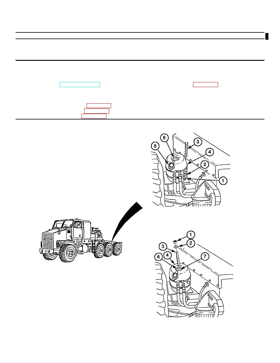
(1) Remove nut (1), washer (2), and tool (3)
from mounting position on brake chamber
(4).
(2) Remove dust cap (5) from access hole (6)
in brake chamber (4).
MUD FLAP REMOVED FOR CLARITY
(3) Insert tool (3) in access hole (6) and align
with slot (7) inside brake chamber (4).
(4) Push tool (3) in slot (7) until it stops.
(5) Turn tool (3) 90 and pull out until it is
seated and stops.
(6) Install washer (2) and nut (1) on tool (3).
(7) Release brake chamber (4) by tightening
nut (1) down (clockwise) until it stops.
Change 3 11-9
|
|
Privacy Statement - Press Release - Copyright Information. - Contact Us |