 |
|||
|
|
|||
|
Page Title:
ENGINE CIRCUIT BREAKER/DIODE/BRACKET REPAIR |
|
||
| ||||||||||
|
|
 TM 9-2320-360-20-2
7-79. ENGINE CIRCUIT BREAKER/DIODE/BRACKET REPAIR
This task covers:
a. Removal
d. Installation
b. Disassembly
e. Follow-On Maintenance
c. Assembly
INITIAL SETUP
Equipment Conditions
Tools and Special Tools
Front wheels turned full left (24V CB/D).
Tool Kit, Genl Mech (Item 54, Appendix F)
Inner fender removed (24V CB/D) (left side
only) (para 16-34).
Engine hood opened (TM 9-2320-360-10).
Batteries disconnected (para 7-61).
Materials/Parts
Doghouse door panel removed (12V CB/D)
Locknuts (2) (Item 70, Appendix G)
Locknut (Item 72, Appendix G)
Lower engine access panel removed (12V CB)
Lockwashers (4) (Item 100, Appendix G)
Lockwashers (2) (Item 102, Appendix G)
Front engine access panel removed (12V CB)
Lockwashers (2) (Item 103, Appendix G)
NOTE
12-volt alternator circuit breaker and
diode are located on top of engine at
left rear.
24-volt alternator circuit breaker and
diode are located on left side of
engine block.
a. Removal
NOTE
Do steps (1) thru (4) for 12-volt circuit
breaker/diode/bracket.
Do steps (5) thru (9) for 24-volt circuit
breaker/diode/bracket.
Tag and mark wires before removing.
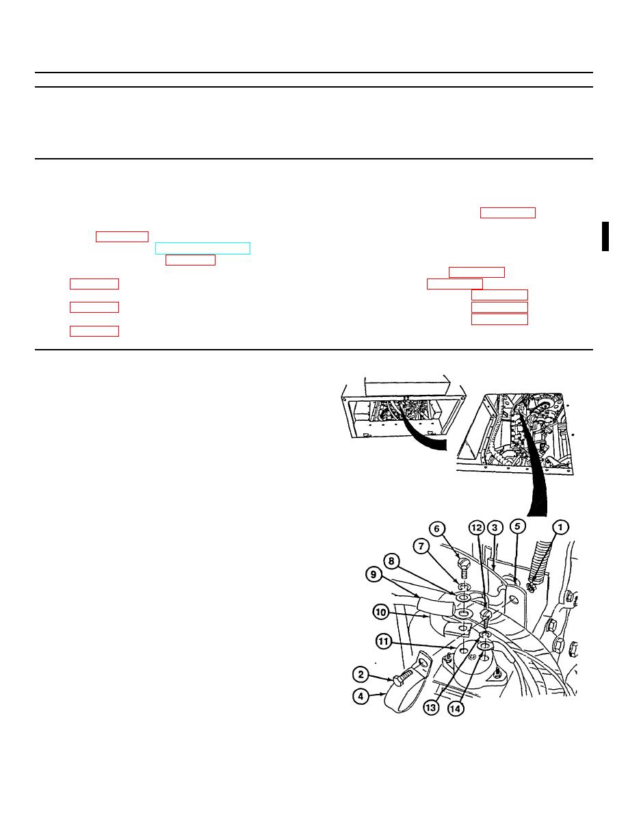
(1) Remove locknut (1), screw (2), ground
wire no. 1435 (3), and cushion clip (4)
from standoff bracket (5). Discard locknut.
(2) Remove screw (6), lockwasher (7), wire
no. 1866 (8), wire no. 1831 (9), and diode
wire (10) from circuit breaker (11).
Discard lockwasher.
(3) Remove screw (12), lockwasher (13), and
wire no. 1622 (14) from circuit breaker
(11). Discard lockwasher.
Change 1 7-245
|
|
Privacy Statement - Press Release - Copyright Information. - Contact Us |