 |
|||
|
|
|||
|
|
|||
| ||||||||||
|
|
 TM 9-2320-360-20-2
7-12.
CIRCUIT BREAKER REPLACEMENT
This task covers:
a. Removal
c.
Follow-On Maintenance
b. Installation
INITIAL SETUP
Equipment Conditions
Materials/Parts
Batteries disconnected (para 7-61).
Tags, Identification (Item 32, Appendix C)
Ties, Cable, Plastic (item 34, Appendix C)
Lockwasher(s) (Item 94, Appendix G)
Tools and Special Tools
Tool Kit, Genl Mech (Item 54, Appendix F)
a.
Removal
CAUTION
Some circuit breakers have dedicated
ground wires. Many circuit breakers
are connected by use of a common
bus bar. When removing bus bar,
ensure connection point is marked.
This will enable proper positioning
during installation.
NOTE
Except for 5 amp DDEC circuit
breaker, circuit breaker wiring is
easily identified by type of
connector. Negative (-) wire has
round connector and positive (+)
wire has pronged connector.
Tag and mark wires before
removal.
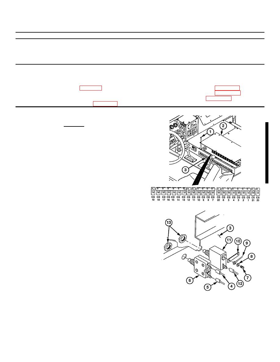
(1) Remove eight screws (1) and cover (2)
from electronic control box assembly (3).
NOTE
Do step (2) only if removing 5 amp
DDEC circuit breaker.
(2) Remove two wires (4 and 5) from rear of 5
amp DDEC breaker (6).
(3) Remove screws (7), lockwashers (8), wire
(9), and bus bar (10) (if installed) from
circuit
breakers
(11).
Discard
(4) Disconnect wire(s) (12) from circuit
breaker (11).
(5) Remove nut (13) from face of circuit
breaker (6 or 11).
(6) Remove circuit breaker (6 or 11) from side
of electronic control box assembly (3).
7-41
|
|
Privacy Statement - Press Release - Copyright Information. - Contact Us |