 |
|||
|
|
|||
|
|
|||
| ||||||||||
|
|
 TM 9-2320-285-24-1
2-33.
HORN SYSTEM MAINTENANCE
a.
Horn and Relay (cont).
STEP
LOCATION
ITEM
ACTION
REMARKS
INSPECTION
4
a. Electrical
Inspect
Replace if cracked, broken,
leads
frayed, defective, or
(5 thru 7)
otherwise damaged. Polish
and horn (17)
corroded terminals to
brightness with fine
sandpaper
b. Relay (8)
Inspect
Replace if cracked, broken,
defective, or terminals
damaged
c.
All other parts
Inspect
Replace if cracked, broken,
distorted, or threads
damaged
ADJUSTMENT
5
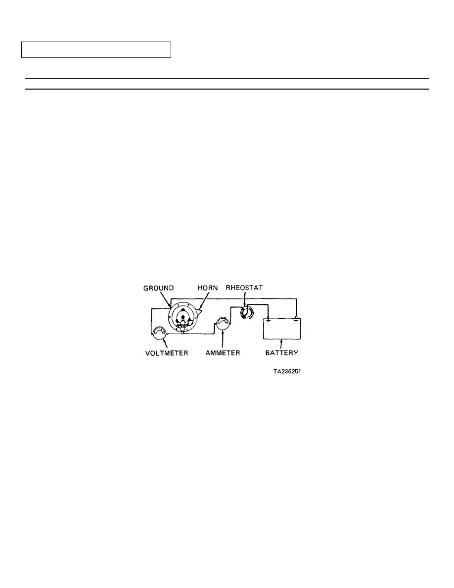
a. Horn (17)
Connect
Connect horn to adjustment
circuit as shown. Adjust
rheostat for 12.4 Vdc
indication on voltmeter
NOTE
Do not stuff rags or other material in horn throat to muffle sound while adjusting. This
changes vibration frequency and results in a false current setting.
b. Adjusting screw
Turn
Turn adjusting screw 1/10
turn at a time, until
ammeter indicates 4.5
amperes. Turn adjusting
screw counterclockwise to
increase current, clockwise
to decrease current; then
disconnect horn from test
circuit
2-369
|
|
Privacy Statement - Press Release - Copyright Information. - Contact Us |