 |
|||
|
|
|||
|
|
|||
| ||||||||||
|
|
 TM 9-2320-269-34-1
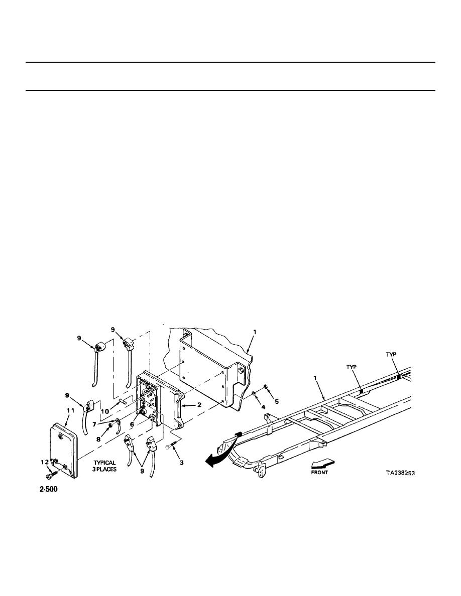
ANTILOCK CONTROL MODULES - CONTINUED
ACTION
LOCATION
ITEM
REMARKS
INSTALLATION
NOTE
Installation procedure is same for all three modules.
9.
Frame (1)
Module control (2)
a. Put in position.
b. Aline with holes in frame.
10.
Module control (2)
Three screws (3)
Screw on, and tighten using 1/2-inch
new lockwashers (4),
socket, ratchet handle with 318-inch
and nuts (5)
drive, and 1/2-inch open-end wrench.
11.
Module ground
Ground wire clip (7)
Put on.
terminal (6)
12.
Ground wire clip (7)
Nut (8)
Screw on, and tighten using 5/16-inch
open-end wrench.
13.
Module control (2)
Connectors (9)
a. Put in position.
b. Press into place using long round-
nose pliers on raised section.
14
New fuse (10)
Press into place.
15
Cover (11) and three
Put in position.
screws (12)
16
Three screws (12)
Screw in, and tighten using 3/8-inch
socket and speeder handle with 1/4-inch
2-500
|
|
Privacy Statement - Press Release - Copyright Information. - Contact Us |
