 |
|||
|
|
|||
|
|
|||
| ||||||||||
|
|
 TM 9-2320-269-34-1
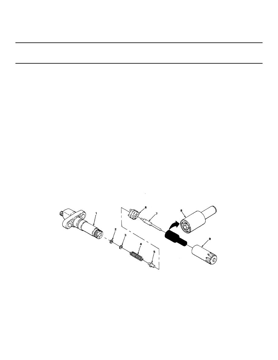
FUEL INJECTORS - CONTINUED
ACTION
LOCATION
ITEM
REMARKS
ASSEMBLY - CONTINUED
CAUTION
Parts of the injector are machined and polished, do not scratch with tools. Machined surfaces are
damaged easily and will damage other parts.
Be sure parts fit together properly to avoid damage to injector.
24.
Body (1)
Two shims (2) and
Put in.
(3) and spring (4)
25
Spring (4)
Seat (5) and
Put on.
plate (6)
26
Plate (6)
Valve (7) and
Put on, and hold.
nozzle (8)
27
Body (1)
Nut (9)
a Screw on finger tight.
b.
Using 12-point 7/8-inch deep-well
socket and torque wrench with 1/2-inch
drive, tighten to 45-65 ft-lb (61 - 88
Nm) of torque.
c.
Take injector and fixture out of vise.
2-254
|
|
Privacy Statement - Press Release - Copyright Information. - Contact Us |
