 |
|||
|
|
|||
|
|
|||
| ||||||||||
|
|
 TM 9-2320-269-34-1
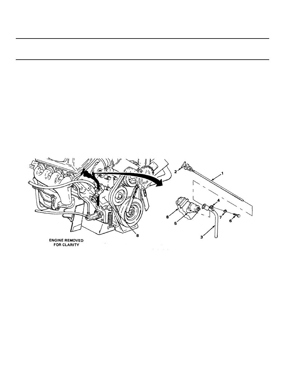
ENGINE OIL LEVEL GAGE AND TUBE - CONTINUED
ACTION
LOCATION
ITEM
REMARKS
INSTALLATION
7.
Cylinder block (8)
Oil level gage
Push in.
tube (3)
8.
Cylinder head
Tube bracket (4)
Put in place.
bracket (5)
9.
Tube bracket (4) to
New lockwasher (7)
Screw in, and tighten using 9116-inch
right water
and screw (6)
socket handle with 112-inch drive.
outlet (5)
10. Oil level gage
Oil level gage (1)
Slide in.
tube (3)
11. Oil level gage (1)
Tee handle (2)
Turn clockwise to tighten.
NOTE
FOLLOW-ON MAINTENANCE: Close right side hood (TM 9-2320-269-20-2).
TASK ENDS HERE
TA238032
2-207
|
|
Privacy Statement - Press Release - Copyright Information. - Contact Us |