 |
|||
|
|
|||
|
Page Title:
CHAPTER 2 OPERATING INSTRUCTIONS |
|
||
| ||||||||||
|
|
 TM 9-1375-213-12-3
TO 11A20-15-1
CHAPTER 2
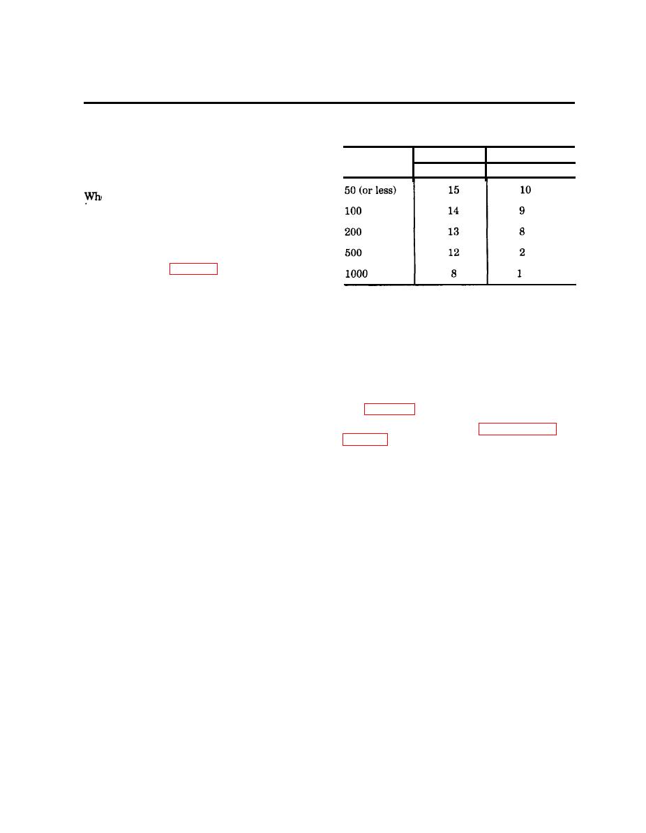
Table 2-1. Number of Blasting Caps That
2-1. GENERAL
May be Fired by One Receiver vs Firing
Lead Length
a. In field use, the receiver may be used as
an expendable or nonexpendable item, When it
No. 18 AWG **
Firing Lead
No. of M6
is necessary or desirable to expend the receiver,
WD-1 Wire
Length* (ft)
it should be placed as close as possible to the
explosive charge (on to of charge, if feasible).
en the receiver is Not to be destroyed, a fir-
ing lead of suffcient length should be used.
The nominal capacity of the receiver is five M6
caps wired in series. The actual number of caps
that may be initiated by a receiver will depend
u on the length and type of firing lead used.
The lead lengths and allowable number of caps
are tabulated in table 2-1 for each t e of wire.
The blasting caps must be connected in series.
Hookup of the firing lead and blasting caps
*Disregard length of M6 cap wires.
should be in accordance with standard electric
priming procedures. Refer to FM 5-250 and
"*M4 caps are M6 caps with an integral long fir-
M 9-1375-213-12 for proper preparation of the
in lead. The lead of each M4 cap must be con-
explosive charges and priming,
Since the
sidered as 100 feet of No. 18 AWG firing lead.
receiver is essentially a low capacity blasting
machine, standard electric priming techniques
c. If receiver is to be left on duty for an
may be employed with it.
extended period before being used to fire the
charge, the length of time a fresh battery will
b. When the receiver is to be used fre-
power the receiver in an on-duty state depends
quently in a nonexpendable manner (on a demo-
upon the type of battery and the temperature
lition range, for example), locate receiver as far
(see para 1-11). If the battery is not fresh, the
away as possible from explosive charge and pro-
on-duty time will be reduced. Criteria on bat-
tect the unit by digging a six inch deep hole in
tery freshness are given in paragraph 3-11 and
the ground. Place receiver in hole, leaving on]
the antenna protruding above the ground.{f
the antenna terminals will be covered with
2-2. PRECAUTIONS
earth, protect them with tape or other water-
proof material. The receiver ma be covered
Operations using demolition tiring device
'
with sandbags or placed in a small wooden box
M122 involve few precautions other than those
required for normal explosive operations that
tainer is used, drill two 1/4-inch holes on the
use conventional electric priming. However,
side of the container, one hole for the antenna
the misfire procedures are different from those
wire and the other hole for blasting wires. The
for normal electric blasting operations. Care
minimum distance that the receiver should be
should be exercised in handling the units of the
placed from the explosive will de end upon
firing device. Both units are ruggedized and
charge size, soil conditions, debris from explo-
water resistant; but the less they are abused,
sion, charge setup, and fragments. For guid-
the greater them reliability.
ance purposes, the minimum safe distance for
receiver placement from a 15 pound charge of
TNT was found to be 15 feet (5.0 meters) in
soft soil and buried below ground level.
2-1
|
|
Privacy Statement - Press Release - Copyright Information. - Contact Us |
