 |
|||
|
|
|||
|
Page Title:
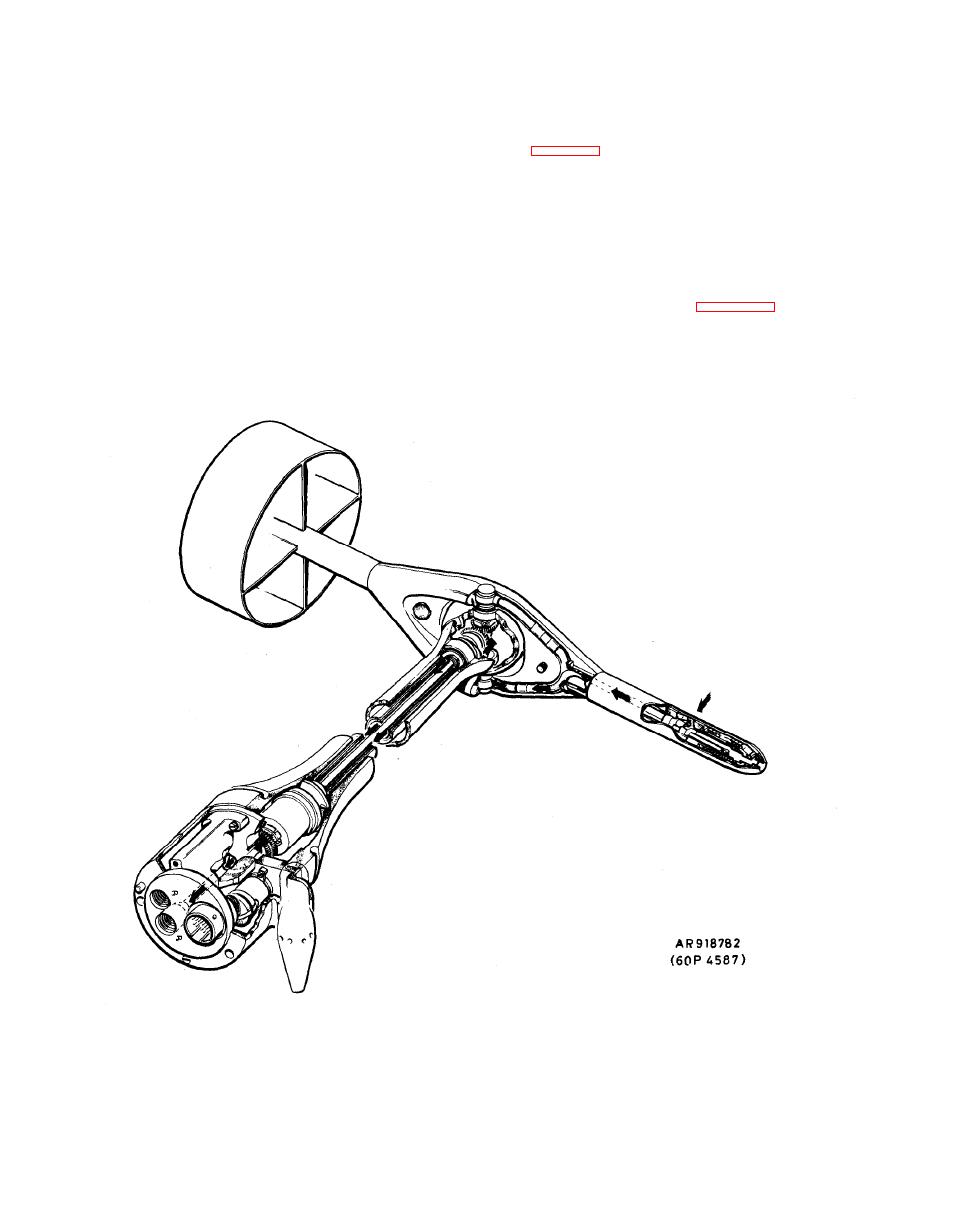
Figure 1-11. AADS Cutaway View showing Static Plumbing. |
|
||
| ||||||||||
|
|
 TM 9-1270-219-13&P
(1) The pitot pressure is conveyed via a rolling
in
turbulent
airflow.
The
fins
and
shroud
of
the
flexible rubber tube in a hollow shaft along the axis of the
tail are built into the shaft from glass-reinforced polyester
neck. See figure 1-10. This pressure transmitting
to make a light and rugged structure.
t e c h n i q u e ensures that air leakage in the AADS pitot line
will not cause errors greater than 0.5 knots at the EPU
pressure transducer. This hollow shaft also transmits the
rotation of the gimbal in the AADS yaw axis to an angular
c. N e c k A s s e m b l y . The neck assembIy has a gimbal
resolver.
joint at its outboard end. The free side of the gimbal is a
(2) Static pressure enters the neck via the other stub
yoke in two halves which, when bolted together, holds the
axle and is transmitted by a second larger concentric
head and tail assemblies and incorporates two nylon stops
hollow shaft through the neck. See figure 1-11. This
w h i c h limit the gimbal travel to 120 in yaw. Pitot and
second shaft transmits gimbal rotation in the yaw axis to
static lines in the yoke are joined to those emerging from
the other angular resolver. The two rotations move the
the head at one end and to the gimbal stub axles at the
shafts of the angular resolvers mounted in the body to
other end.
|
|
Privacy Statement - Press Release - Copyright Information. - Contact Us |
