 |
|||
|
|
|||
|
Page Title:
Section V. LINKAGE ASSEMBLY TROUBLESHOOTING |
|
||
| ||||||||||
|
|
 TM 9-1270-212-14&P
Section V. LINKAGE ASSEMBLY TROUBLESHOOTING
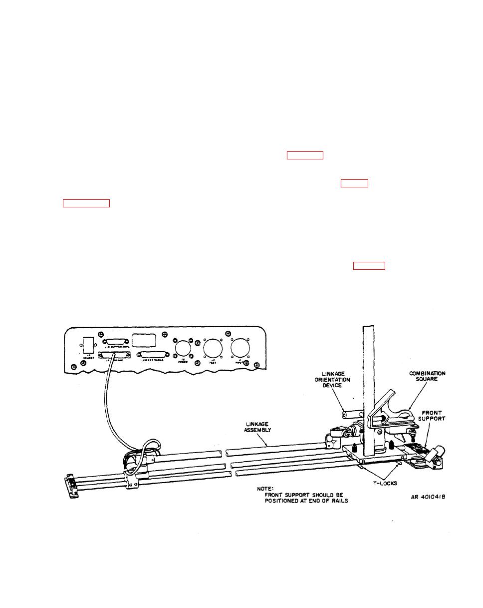
position. Use the LOD bubble and adjust the
4-17. General.
swivel frame if necessary; this insures that the
rails are not twisted.
This section provides troubleshooting procedures for the
gunner and pilot linkage assemblies by using the test set.
b. Connect the test set, LOD, and linkage assembly as
The tests should be performed on the bench. The tests are
shown in figure 4-10.
identical for the two linkage assemblies.
c. Adjust the LOD azimuth angle and elevation angle
with a combination square (fig. 4-10).
procedures
a. Perform the test-set preliminary
d. Set the POWER switch to ON-60 HZ if a 60-Hz
power source is used or to ON-400 HZ if a 400-Hz power
source is used.
NOTE
When the test is performed on a bench, the
switch to AC V.
linkage assembly must be placed on a level
surface with the mounting brackets and rails
also leveled. Lock the LOD in the 0-degree
|
|
Privacy Statement - Press Release - Copyright Information. - Contact Us |
