 |
|||
|
|
|||
|
Page Title:
Boresighting Procedures (Gunner's Station). |
|
||
| ||||||||||
|
|
 TM 9-1270-212-14&P
f. Set the circuit breakers on the dc breaker panel as
NOTE
follows:
The weight of the borescope in the LOD
GEN FIELD to closed (on)
bracket can cause the rails to flex and provide
inaccurate sightings. Therefore, when sighting,
support the weight of the borescope while
DC VOLT METER (or DC VM) to closed (on)
making sure the tapered pin is in full contact
with the borescope bracket.
CAUTION LT (or CAUT LT) to closed (on)
h. View through the borescope and adjust the LOD in
INV MAIN (or [NV) to closed (on)
azimuth and elevation until the intersection of the
crosshairs of the borescope reticle coincides with the
GEN BUS RESET to closed (on).
intersection of the crosshairs of the gunner's HSS target on
the center target.
g. Check that the ELEC PWR EMER OFF switch on the
gunner's left pedestal panel (or gunner's miscellaneous
i. Tighten the azimuth locking knob and the elevation
panel) is set to ELEC PWR.
angle locking knob.
h. Set the electrical power control panel switches as
j. Being careful not to pull or push against the
follows:
borescope in the LOD, recheck the center target alignment
of step h. Remove the borescope.
INV (or ALTNR) to MAIN (or ON)
BAT (or BATTERY) to ON (RUN)
4-6).
NON-ESS BUS (or NON-ESNTL BU) to NORMAL.
NOTE
4-9. Boresighting Procedures (Gunner's Station).
The B1 resolver is very sensitive to adjustment.
A very slight adjustment results in a large
a. Turn the MODE SELECT switch on the TOW control
displacement in the TSU LOS.
panel to STBY TOW, and set the MASTER ARM switch on
the pilot armament control panel to STBY and the
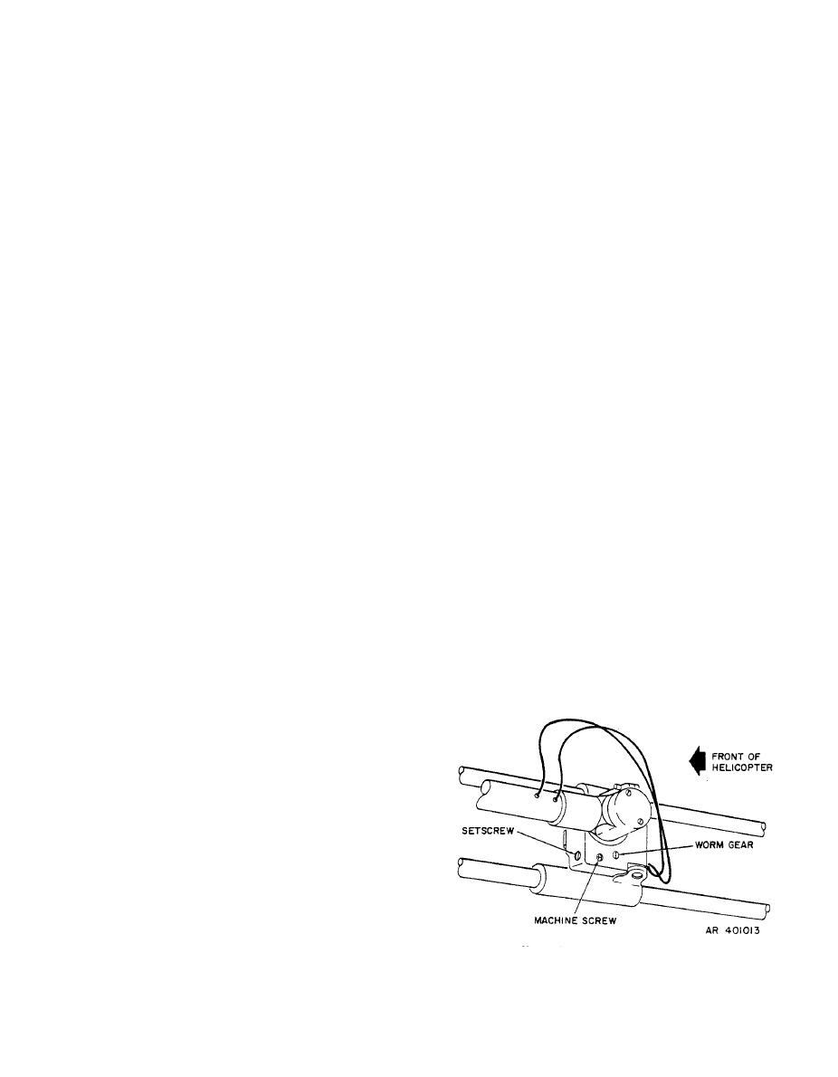
l. While viewing through the TSU, hold the ACQ TRK
left-hand-grip MAC switch to HI.
STOW switch to ACQ. The technician viewing through the
TSU shall verbally inform the technician in the pilot's
b. Position the gunner and pilot linkage assemblies in
compartment to adjust the B1 resolver worm gear to bring
their respective BIT brackets.
the TSU reticle crosshairs over the TSU optics target
elevation crosshair.
c. Push BIT switch and confirm that the HSS GO light
illuminates.
d. Insure that the LOD rail clamp base is locked in the
O-degree position. Attach the LOD to the forward end of
the gunner's rails with the bubble forward. Tighten the
T-locks on the LOD T-bars until the LOD is firmly attached
to the rails.
e. Attach the gunner linkage assembly to the magnet on
the LOD.
f. Slightly loosen the azimuth locking knob and the
elevation angle locking knob.
g. Insert the borescope in the LOD.
|
|
Privacy Statement - Press Release - Copyright Information. - Contact Us |
