 |
|||
|
|
|||
|
Page Title:
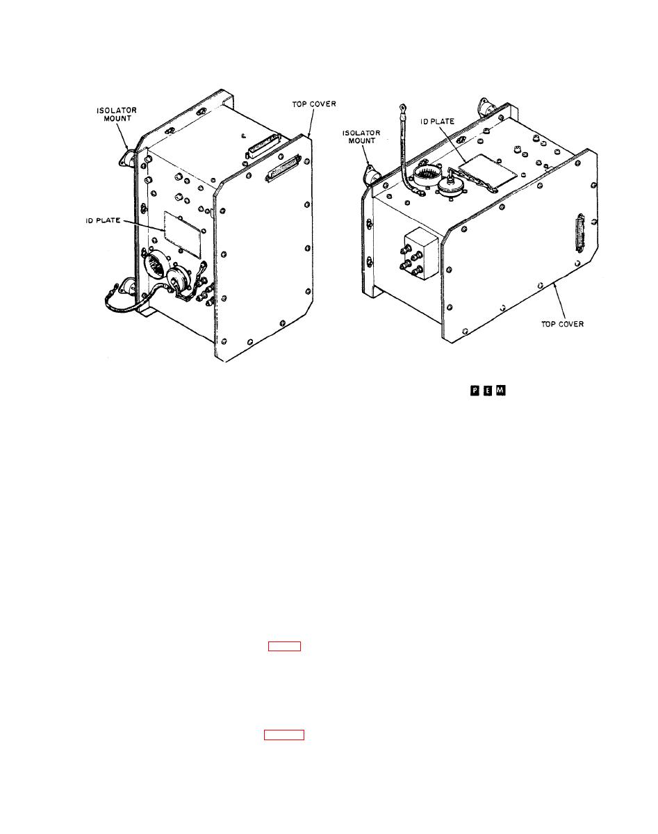
Figure 1-5. Electronic interface assemblies |
|
||
| ||||||||||
|
|
 TM 9-1270-212-14&P
VIEW B. EIA FOR XM136
VIEW A. EIA FOR XM128
AR 401060B
AH-1S
AH-1S (MOD)
Figure 1-5. Electronic interface assemblies
Table 1-1. Dimensions and Weights of HSS Components
operation results in the display of a go signal. Failures are
indicated for the gunner linkage, the pilot linkage, and the
EIA. The logic circuits differ between the two EIAs and the
Length
Wt.
Component
Width
Depth
logic circuit cards are not interchangeable and have
(in.)
(lb)
(in.)
(in.)
(assembly)
different unit designators (A10 in the EIA for XM128 and
Al5 in the EIA for XM136). The electrical difference
Gunner helmet sight
0.75
6
5
10
between A10 and Al5 is in the resistor network used
during test of the linkages. Logic card Al5 also has separate
0.75
6
5
Pilot helmet sight
10
test inputs for the gunner and pilot linkages.
4.00
36
3
Pilot linkage
5
1-14. Extension Cable.
4.00
5
3
36
Gumer linkage
An extension cable is required between the aft end of
the gunner linkage assembly and the EIA (fig. 1-2). The
Electronic interface:
cable is secured to the overhead canopy supports and has a
From XM128
7.5
15.00
6.5
12
mounting bracket at the forward end and a rectangular
From XM136
7.5
15.00
6.5
13
cable connector at the aft end.
Extension cable
2.00
3
50
1-15. Tabulated Data.
a. Dimensions and Weights. The dimensions and
Total
26.50
weights of the HSS components are given in table 1-1.
|
|
Privacy Statement - Press Release - Copyright Information. - Contact Us |