 |
|||
|
|
|||
|
Page Title:
Figure 3-9. Reticle missile lamp assembly-partial exploded view |
|
||
| ||||||||||
|
|
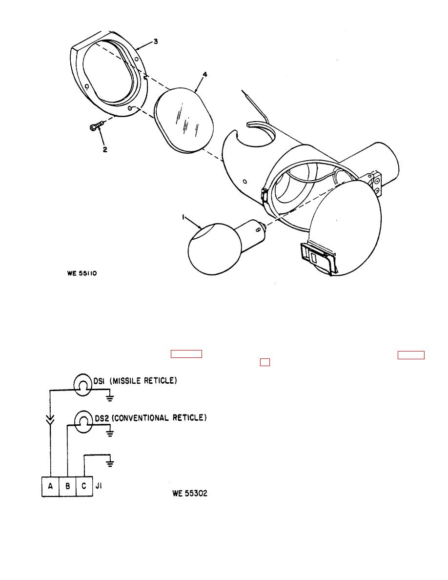 1 - Lamp, sgl cont, 28V, 8624583
2 -- Screw, 2-56 x 1/4, (3),
3-- Plate, 8624587
MS51959-3
4-- Mirror, 11727579
Figure 3-9. Reticle missile lamp assembly-partial exploded view.
housing opening. Position washer (8) secure with screw
(3) Install remaining parts in reverse order of
(7).
removal.
(2) Position and solder wires to the receptacle
assembly in accordance with wiring diagram (fig. 3-10).
3-15. Removal of Objective Tube Assembly Fig. 3-
a. Disassembly. Remove items 2 and 3. Pry tube
assembly (4) from locating pin and lift from housing.
b. Assembly.
(1) Position tube assembly (4) over locating
pin on filter housing, secure with items 3 and 2.
(2) Remove eight screws (1), seven around
face of tube assembly and one on top surface.
(3) Using adapter, attached to sealing gun.
inject sealing compound, MIL-S-11030, into the eight
holes to affect a perfect seal between tube and housing.
(4) Install screws.
Figure 3-10. Receptacle assembly wiring diagram
3-13
|
|
Privacy Statement - Press Release - Copyright Information. - Contact Us |
