 |
|||
|
|
|||
|
Page Title:
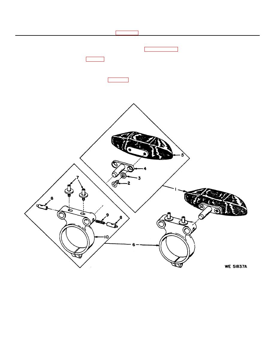
Figure 3-2. Headrest and bracket assembly exploded view |
|
||
| ||||||||||
|
|
 1-Setscrew, 6-32 x 1/8 (3)
3-Screw, 10-24 x 1/2, MS16995-36
5-Washer, flat 7/32 id, 221432
MS51021-21
4-Washer, lock, No. 10, MS35333-73
6-Headrest and bracket assembly
2-Eyeguard, 10549867
Figure 3-1-Continued.
(1) Guide bracket assembly (6) over the
before removing eyepiece assembly.
Refer to
eyeguard and position on neck of the eyepiece
paragraphs 3-4 a and g.
assembly. Install items 5 and 4, secure with item 3.
(2) Install headrest (1, fig. 3-2) into either
a. Removal.
positioning hole in bracket assembly for convenience of
(1) Remove item 1.
Unscrew eyepiece
the operator.
assembly (2) and remove from housing.
(2) Reach into housing and remove packing
3-5.
Replacement of Eyepiece Assembly(Fig. 3-3)
(3).
Note:
Remove headrest and bracket assembly
b. Inspection.
(1) Inspect the eyepiece assembly.
Check
9-Spring, compression, 15 coils,
4-Support, 11730901
1-Headrest
862453677
5-Headrest, padded, 10553476
2-Screw, 1/4-28 x 3/8, (2)
10-Bracket, 8624535
6-Bracket assembly, 8624562
MS51958-77
7-Screw, 8-36 x 1-1/8, (2) 8624676
3-Washer, lock 1/4 scr size, (2)
8-Plunger (2), 8624675
MS35338139
Figure 3-2. Headrest and bracket assembly exploded view.
3-3
|
|
Privacy Statement - Press Release - Copyright Information. - Contact Us |
