 |
|||
|
|
|||
|
Page Title:
RANGEFINDER LINK CONNECTOR ASSEMBLY DISASSEMBLY |
|
||
| ||||||||||
|
|
 TM 9-1220-220-34
4-27.
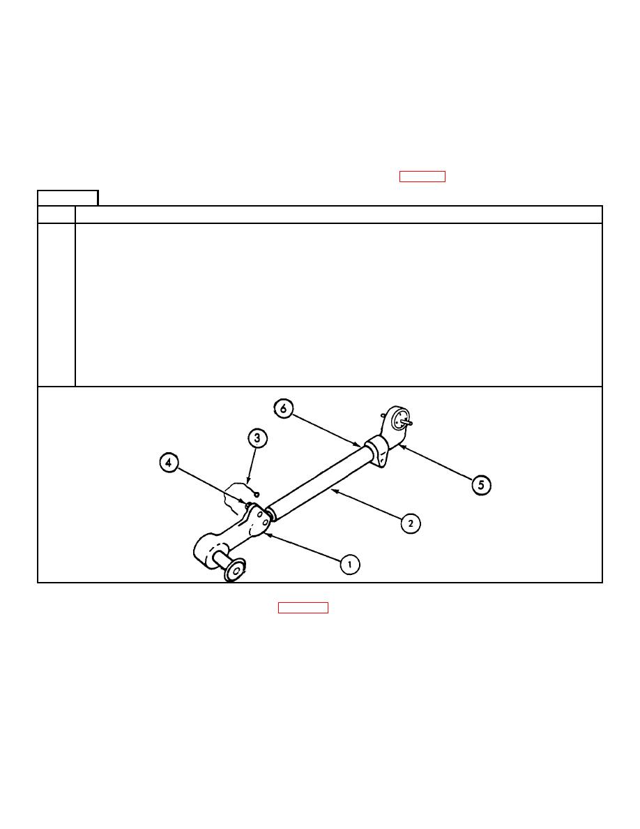
RANGEFINDER LINK CONNECTOR ASSEMBLY DISASSEMBLY
TOOLS:
3/4" open end wrench
Scriber
PERSONNEL:
One
EQUIPMENT CONDITION: Rangefinder link connector assembly on work bench
PRELIMINARY PROCEDURE: Remove rangefinder link connector assembly (para 4-4, frames 2 and 3)
FRAME 1
Step
Procedure
Step
Procedure
NOTE
Count and record number of turns in steps 3 and 6.
1.
Using scriber, mark the position of the rear connector assembly (1) on tube assembly (2).
2.
Cut lead wire seal (3).
3.
Using 3/4" wrench, loosen capscrews (4).
4.
Holding tube assembly (2) turn rear connector assembly (1) counterclockwise and remove,
counting the number of turns while removing it.
5.
Using scriber, mark the position on connector assembly (5) on tube assembly (2).
6.
Using 3/4" wrench, loosen capscrew (6).
7.
Holding tube assembly (2) turn connector assembly (5) clockwise, and remove, counting
the number of turns while removing it.
END OF TASK
Para 4-27 Vol II
4-70
|
|
Privacy Statement - Press Release - Copyright Information. - Contact Us |
