 |
|||
|
|
|||
|
Page Title:
Remove 30MM Gun Wire Deflector. |
|
||
| ||||||||||
|
|
 TM 55-1520-238-S
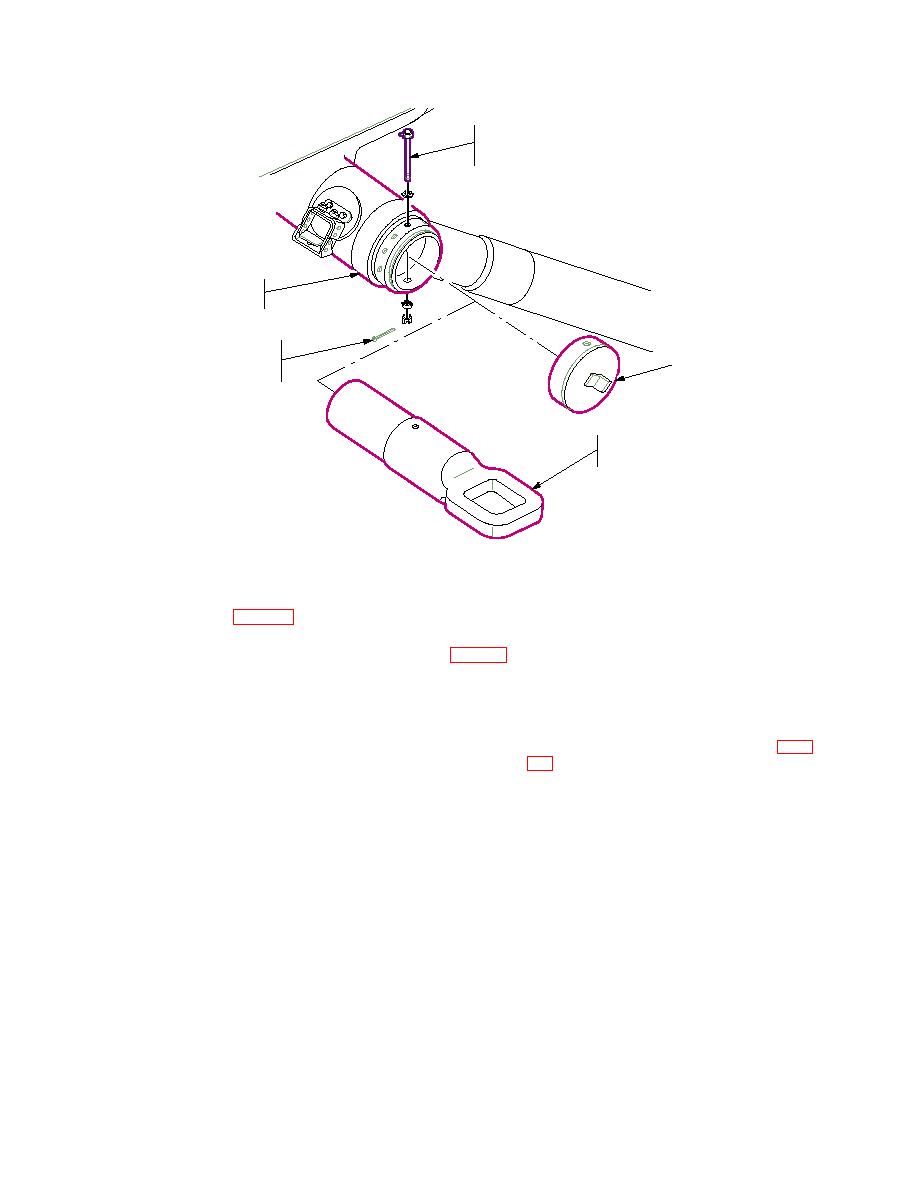
STUD (WITH ONE NUT IN PLACE)
REMOVE IN DIRECTION OF
BEST CLEARANCE
MAIN LANDING GEAR
CROSS TUBE
COTTER PIN AND NUT
REMOVED FROM ONE
END CAP
END OF STUD ONLY
FORWARD FUSELAGE
TIEDOWN FITTING
NOTE:
LEFT SIDE SHOWN
TYPICAL FOR BOTH SIDES
M05-012B
c. Stow. Stow wrapped cutters on floor of
b. Install Tiedown Fittings. Slide tiedown
pilots station.
fittings (item 6, table 21) into left and right
ends of each main landing gear cross tube.
Aline holes in fittings and cross tube, and
install removed studs, washers, and nuts.
a. Secure Stabilator Shims. Secure shims
c. Stow Removed Cross Tube End
in place until installed. Do not remove
shims from spacers.
material (D5) secured with tape (D13).
b. Install
Stabilator
Actuator
Sup-
Stow wrapped end caps on floor of pilots
station.
nect actuator rod end to support end fitting.
211.9 Remove 30MM Gun Wire Deflector.
Use removed stabilator pivot and actuator
a. Remove Wire Deflector.
rod end hardware.
TM 1-1520-238-23.
c. Static Wicks. To prevent damage to stat-
b. Component Wrap. Wrap deflector as-
ic wicks, loosen one screw and remove oth-
sembly with cushioning material (D5) se-
er in each wick. Rotate wick 180 and tight-
cured with tape (D13).
en screw. Reinstall first screw in stabilator.
c. Stow. Stow deflector assembly securely
d. Access Covers. Reinstall stabilator ac-
in catwalk area.
cess covers.
e. ComponentWrap. Wrap stabilator with
211.10 Remove Main Landing Gear Lower Wire
barrier material (D1) then with cushioning
Cutters.
material (D5) secured with tape (D13).
a. Remove Wire Cutters. Remove left and
211.12 Number Helicopters.
right lower main landing gear wire cutters
(TM 1-1520-238-23).
NOTE
Helicopters must be configured differently
b. Component Wrap. Wrap cutters with
within each load depending on whether
cushioning material (D5) secured with
they are to be loaded nose first or tail first.
tape (D13).
|
|
Privacy Statement - Press Release - Copyright Information. - Contact Us |
