 |
|||
|
|
|||
|
Page Title:
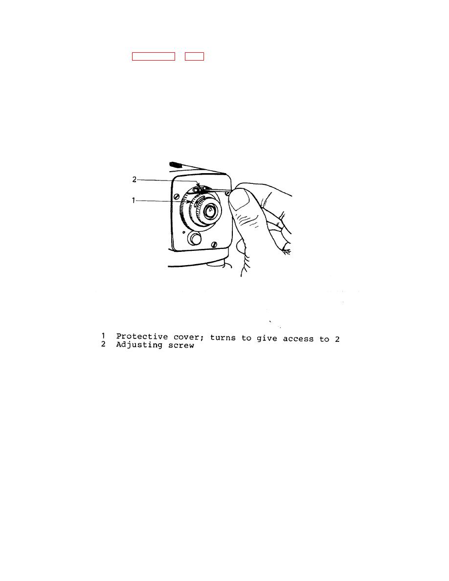
Figure 4-3. Adjusting the Line of Sight |
|
||
| ||||||||||
|
|
 TM 5-6675-329-13 & P
(2)
Adjusting (see Figures 4-2 and 4-3).
The instrument is still at D. The line of sight is adjusted by shifting the reticle plate slightly. This is
done with the capstan-headed adjusting screw (2) which can be seen after turning the black, protective cover (1) to the
left. Using the adjusting pin from the instrument container, carefully turn the adjusting screw (2) until the horizontal hair
gives the computed, correct reading a4 on the staff B. The last turn of the adjustment screw (2) should be clockwise, i.e.
to the left. Close the protective cover (1) by turning it to the right to its stop. Finally repeat the test (4-10 b. (1)) to verify
the adjustment.
Figure 4-3. Adjusting the Line of Sight
4-10
|
|
Privacy Statement - Press Release - Copyright Information. - Contact Us |
