 |
|||
|
|
|||
|
Page Title:
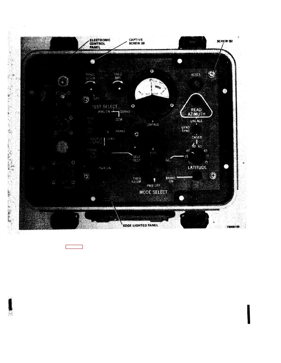
Figure 3-1. Electronic Control Panel. |
|
||
| ||||||||||
|
|
 TM 5-6675-250-34
( 7 ) Remove five screws securing edge-lighted
p a n e l to control panel.
a. Removal.
( 8 ) Using orangewood sticks, lift edge-lighted
(1) Place
MODE
SELECT
switch
to
GC
p a n e l off control panel.
position.
b. Installation.
(2) Place TEST SELECT switch to SOURCE
(1) Place edge-lighted panel over connector and
VOLTAGE position.
s e a t properly.
(3) Loosen MODE SELECT knob setscrews
(2) Install five mounting screws to secure panel
with 5/64-inch hex wrench and remove knob from
in place.
switch shaft.
( 3 ) Install BIAS control locking knob on BIAS
(4) Loosen
TEST
SELECT
knob
setscrews
switch shaft.
w i t h 0.050-inch hex wrench and remove knob from
(4) Apply MIL-S-22473, Grade N, Form R
switch shaft.
( 5 ) Loosen BIAS knob setscrews with 5/64-inch
p r i m e r to the setscrew and allow to air dry. Then
hex wrench and remove knob from switch shaft.
a p p l y MIL-S-46163 Grade N, Type II, to the first
(6) Unscrew BIAS control locking knob from
few threads of the setscrews.
BIAS control shaft and remove.
Change 1
|
|
Privacy Statement - Press Release - Copyright Information. - Contact Us |