 |
|||
|
|
|||
|
Page Title:
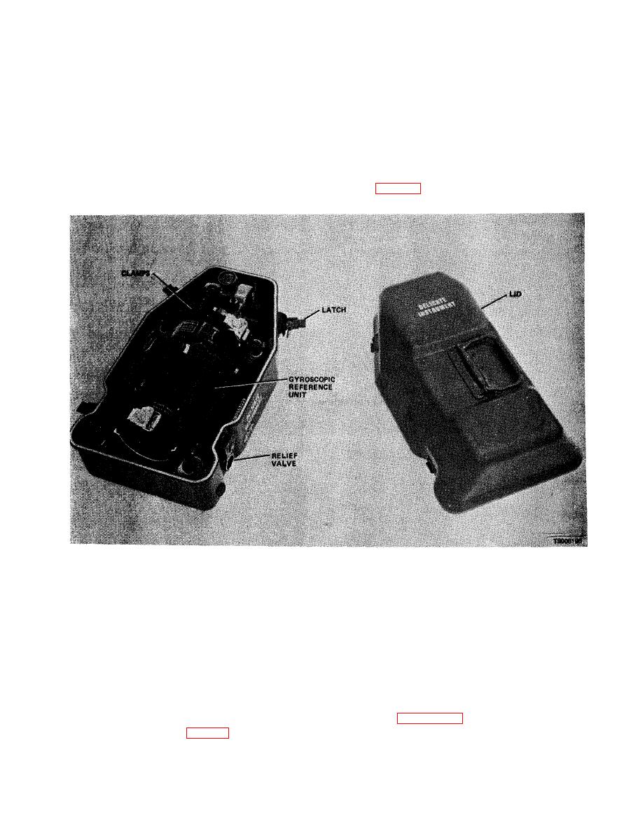
Figure 2-95. Transit Case-Packing and Unpacking. |
|
||
| ||||||||||
|
|
 TM 5-6675-250-34
white stripes on the tripod with the white stripes on
body of the instrument and tighten.
the GRU housing.
(6) While holding the equipment, loosen the
(9) Release the horizontal lock and tighten the
three locking clamps on the tripod and retract the
vertical lock on the theodolite.
tripod legs. Lock the legs in the retracted position.
Compress the legs against the GRU. If extended,
CAUTION
Exercise care when positioning the GRU in
retract the tripod spades into the legs.
the Transit Case. Incorrect positioning can
(7) Align the alidade index stripe with the
cause damage to the reference mirror.
theodolite index stripe.
(10) With the GRU and the tripod assembled,
(8) Maintain the theodolite telescope pointing
secure the equipment in the transit case with the
upward and parallel to the vertical plane, align the
clamps (fig. 2-95).
bottom section of the transit case.
b. Installation
(3) Release the clamps that secure the GRU in
(1) Press the pressure-relief valve on the transit
the case.
case to relieve internal pressure.
(4) Lift the GRU from the transit case.
(2) Unlatch and separate the lid section from the
Section V. FAILURE ANALYSIS
Circuits corresponding to the test jacks and in-
dications required during testing are reflected in
Monitoring and checkout of signals between the
table 2-93. Figure 2-97 illustrates wave forms that
ECU and the GRU are provided through the in-
should appear during applicable tests, using an
terconnect breakout box (fig. 2-96). Each pair of test
jacks on the breakout box are identified by a letter.
2-89
|
|
Privacy Statement - Press Release - Copyright Information. - Contact Us |