 |
|||
|
|
|||
|
Page Title:
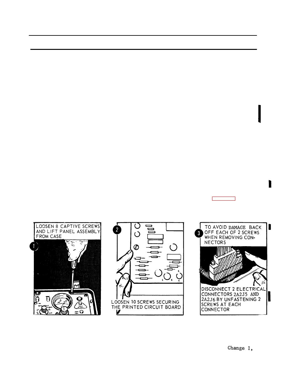
Figure 2-72. Removal of printed circuit board |
|
||
| ||||||||||
|
|
 TM 5-6675-250-34
Table 2-1. Troubleshooting - Continued
MALFUNCTION
TEST OR INSPECTION
CORRECTIVE ACTION
Figure 2-71. Deleted.
GYROSCOPIC REFERENCE UNIT (GRU)
13. THEODOLITE MOUNTING PLATE FAILS TO ROTATE OR ROTATES IMPROPERLY WITH MODE SELECT IN SELF-
TEST POSITION AND TEST SELECT SWITCH IN THE SERVO POSITION.
Step 1. Inspect printed circuit board for evidence of damage or failed components.
a. Loosen the eight captive screws and lift the electronic control panel assembly from the case (figure 2-72).
CAUTION
TS 006311
b. Unfasten ten screws securing the printed circuit board to the mounting brackets and loosen the
board to obtain access to electrical connectors.
2-59
|
|
Privacy Statement - Press Release - Copyright Information. - Contact Us |
