 |
|||
|
|
|||
|
Page Title:
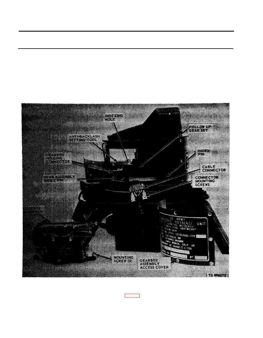
Figure 2-33. Gearbox assembly removal. |
|
||
| ||||||||||
|
|
 TM 5-6675-250-34
Table 2-1. Troubleshooting - Continued
MALFUNCTION
TEST OR INSPECTION
CORRECTIVE ACTION
Install the anti-backlash setting tool (fig. 2-33) into the index hole of the upper gear half of the
(5)
follow-up gear set, with the handle of the tool towards the main connector cover.
(6) Place the thumb on one end of the gear set and the index finger on the other and slide the two
gear halves together so the ends are flush.
2-26
|
|
Privacy Statement - Press Release - Copyright Information. - Contact Us |
