 |
|||
|
|
|||
|
Page Title:
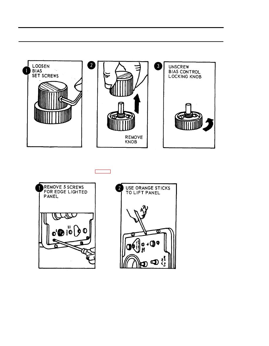
Figure 2-31. Removal of BIAS control knobs. |
|
||
| ||||||||||
|
|
 TM 5-6675-250-34
Table 2-1. Troubleshooting - Continued
MALFUNCTION
TEST OR INSPECTION
CORRECTIVE ACTION
TS 006270
e. Unscrew BIAS control locking knob from BIAS control shaft remove.
TS 006271
g. Using orangewood sticks, lift edge-lighted panel off control panel.
h. Install a new edge-lighted panel over connector and seat properly.
i. Install five mounting screws to secure panel in place.
5. TEST METER FAILS TO PROVIDE REQUIRED INDICATIONS DURING SELF-TEST OPERATION
Step 1. Check for defective gearbox assembly in SERVO and GYRO test modes by performing the following test.
Apply power and check operation as follows:
2-24
|
|
Privacy Statement - Press Release - Copyright Information. - Contact Us |
