 |
|||
|
|
|||
|
Page Title:
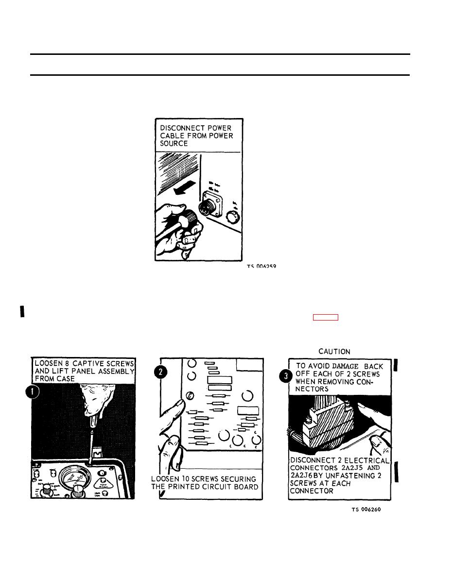
Figure 2-20. Removal of ECU and GRU power cables. |
|
||
| ||||||||||
|
|
 TM 5-6675-250-34
Table 2-1. Troubleshooting - Continued
MALFUNCTION
TEST OR INSPECTION
CORRECTIVE ACTION
b. Inspect cable for damaged connectors and broken or frayed wires and insulation.
(1). Replace a damaged cable.
(2). Connect the interconnect cable to the GRU and ECU receptacle.
Step 3. Check for defective theodolite bright control (2A2R1) or MODE SELECT switch (2A2S3).
a. Loosen the eight captive screws and lift the electronic control panel assembly from the case (fig. 2-21).
Change 1
2-16,
|
|
Privacy Statement - Press Release - Copyright Information. - Contact Us |