 |
|||
|
|
|||
|
Page Title:
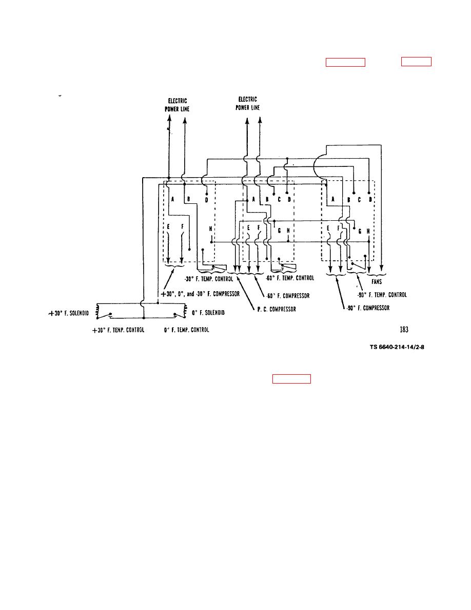
Figure 2-8. Wiring Diagram for Cloud- and Pour-Point Apparatus. |
|
||
| ||||||||||
|
|
 TM 5-6640-214-14
(3) Cloud-and pour-point apparatus. The cloud- and pour-point apparatus (para 2-25) is wired (fig. 2-8) to
maintain the baths of the apparatus at the temperatures prescribed for the performance of the pour-point tests (ASTM D-
97). Electric power for the apparatus is obtained from the main 110-volt electric line within the laboratory.
Figure 2-8. Wiring Diagram for Cloud- and Pour-Point Apparatus.
(4) Channel Point Apparatus. The channel point apparatus (para 2-27) is wired to maintain the apparatus at
the temperature prescribed for the performance of the channel point test. Electric power for the apparatus is obtained
from the main 110-volt electric line within the laboratory.
b. Gas Lines. The gas lines of the cabinets are connected by means of union couplings or, when necessary, by
flexible metal braided hose to provide a continuos flow of gas to all parts of the laboratory. After all cabinets have been
connected, the gas lines are connected to the main source of gas. Gas is supplied from cylinders or tanks containing
bottled gas, such as propane gas, or from gas lines when available. Bottled gas cylinders or tanks are normally located
outside of the laboratory buildings. In extremely cold climates, the gas containers must be protected by a building or
shed to prevent freezing.
2-11
|
|
Privacy Statement - Press Release - Copyright Information. - Contact Us |
