 |
|||
|
|
|||
|
Page Title:
General Maintenance Instructions |
|
||
| ||||||||||
|
|
 5-9. General Maintenance Instructions
(8) All attaching and mounting hardware for
tightness.
a. In Process Inspection. During repair, inspect
the balanced magnetic switch after removal of parts for
b. Cleaning. Use a mild solution of warm water
defects not visible when the unit is assembled. Continue
and liquid soap to clean housing and cover parts. After
the inspection during assembly to insure that parts are
cleaning rinse parts with cold water to remove any soap
properly assembled and that the unit will meet
solution and dry thoroughly. Use a soft camel's-hair
performance standards. During the repair process,
brush or vacuum cleaner with suitable attachment to
inspect the balanced magnetic switch for the following:
remove accumulated dust from components within the
alarm switch housing.
(1) Components for cleanliness.
c. Repair Precautions. Use standard maintenance
(2) Painted surfaces for deterioration or
practices and observe the following precaution: Use
scratches.
exact replacement parts. A part with the same electrical
(3) Screws for damage or corroded threads.
value or function but different physical size will cause
trouble.
(4) Nuts and screw threads to insure they are
not stripped.
5-10. Disassembly and Assembly
(5) Components for breaks, chips, cracks.
No specific procedures are required to disassemble and
(6) Moving parts for wear.
assemble the balanced magnetic switch. Component
locations and attaching parts are illustrated in figure C1.
(7) Electrical wiring for fraying or other
damage.
Section V. DS TESTING PROCEDURE
5-11. General
(1) VOM TS352B.
This section contains a performance standard test
(2) Test lead (2).
procedure for use in determining if the balanced
magnetic switch is operating satisfactory.
The
(3) Screwdriver, slot-end.
procedure should be used following repair and prior to
(4) Ruler, six-inch.
equipment installation.
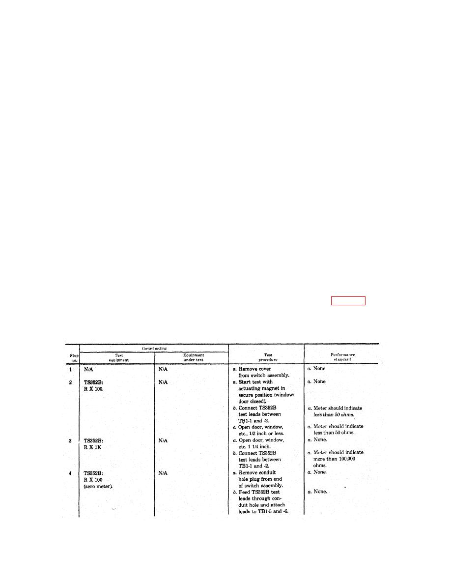
5-12. Performance Standards
a. Test Equipment and Materials.
Table 5-1. BMS Performance Standards
5-2
|
|
Privacy Statement - Press Release - Copyright Information. - Contact Us |
