 |
|||
|
|
|||
|
Page Title:
CHAPTER 6 FUNCTIONING OF EQUIPMENT |
|
||
| ||||||||||
|
|
 CHAPTER 6
FUNCTIONING OF EQUIPMENT
Section I SIMPLIFIED FUNCTIONAL OPERATION
6-1. General
The processor/detector vibration signal senses vibrational energy in the frequency range between 10 kHz and 15 kHz
which may be generated during forced penetration attempts. The equipment is insensitive to vibrational energy below 10
kHz and above 15 kHz.
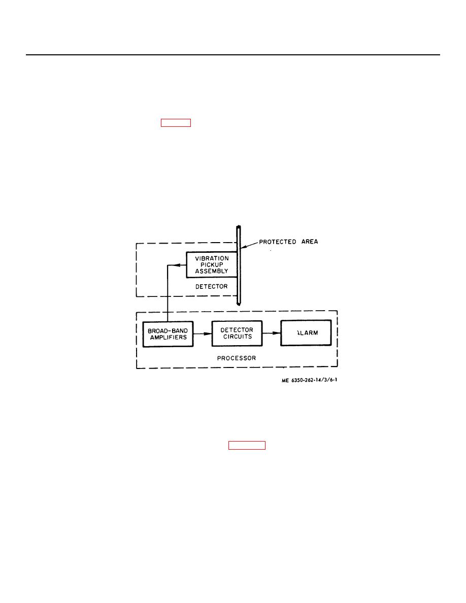
6-2. Simplified Functional Operation (fig. 6-1)
a. The processor/detector vibration signal contains a processor which processes data received from the detectors.
Each detector enclosure contains a vibration pickup assembly which has a response between
10 kHz and15 kHz (audible range). Vibrational energy received by the detector is amplified by broadband amplifier
(three amplifiers stagger tuned) in the processor. The output from the broadband amplifier is coupled directly to the
detection circuits.
b. The detection circuits recognize a vibrational energy impulse of 100 milliseconds duration or longer. Four
detected vibrational energy impulses of 100 milliseconds duration occurring within a 15 second period will activate the
alarm or a single continuous vibration energy impulse of 4.5 seconds duration or longer will also activate the alarm.
Figure 6-1. Processor/detector vibration signal simplified block diagram.
Section II DETAILED FUNCTIONAL OPERATION
6-3. Detailed Functional Analysis
A detailed block diagram of the vibration detection system (fig. FO-2, located at rear of manual highlights the functional
areas within the detector and the processor. Signal flow paths between functional areas are shown which relate
operation between functions.
a. Detector. This unit contains a vibration pickup assembly and a preamplifier. The vibration pickup assembly
sense vibrational energy over the vibrational gravity range of 0.01 g to 1.6 g in the frequency range between 10 kHz and
15 kHz. The vibration pickup assembly drives a preamplifier Q1 which is in cascade with broadband amplifier Q1 in the
processor The preamplifier has an adjustable gain of 20 dB which is controlled by GAIN control R6 for setting optimum
levels as required at each detector location. The output impedance of each detector is very high
6-1
|
|
Privacy Statement - Press Release - Copyright Information. - Contact Us |