 |
|||
|
|
|||
|
Page Title:
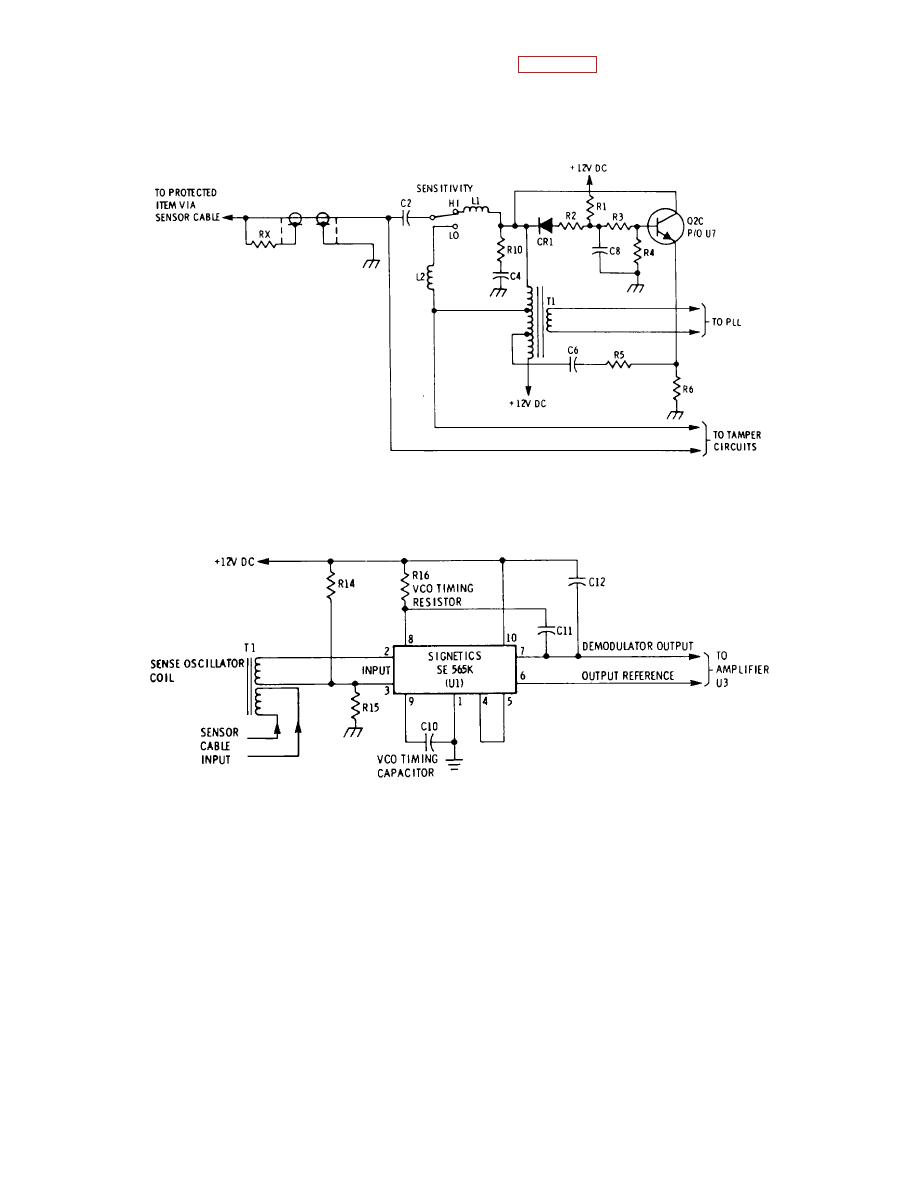
Figure 6-2. Sense Oscillator with Input Filter, Schematic Diagram |
|
||
| ||||||||||
|
|
 g. Power Supply. A schematic of the power supply is shown in Figure 6-8. CR7 is used to prevent damage in the
case of accidental polarity reversal. R40 and C20 filter fast rise voltage spikes which may appear on the input line. U2,
a monolithic integrated circuit, is the principal regulator an(d furnishes +12 VDC to the more sensitive parts of the circuit,
that is, to all circuitry except the logic an(l relays. R44 an(d CR8 form a second regulator which furnishes +12 VDC
(nominal) to the logic and relays.
ME 6350-262-14/13-6-2
Figure 6-2. Sense Oscillator with Input Filter, Schematic Diagram
ME 6350-262-14/13-6-3
Figure 6-3. Phase Lock Loop, Schematic, Diagram
6-4
|
|
Privacy Statement - Press Release - Copyright Information. - Contact Us |