 |
|||
|
|
|||
|
Page Title:
Chapter 4 FUNCTIONING OF EQUIPMENT |
|
||
| ||||||||||
|
|
 CHAPTER 4
FUNCTIONING OF EQUIPMENT
decoded in the receiver. After the receiver decodes the
4-1. General
status present at the control unit it provides this status to
This chapter contains the description of the operation of
the Status Indicator of the Monitor Unit which then sets
the data transmission system type I (DTS-I). The DTS-I
appropriate alarm or status conditions. Paragraph 1-8
provides a secure method of transmitting the status at
gives the detailed purpose and use of the DTS-I and
the control unit of the J-SIID system to the monitor unit of
the system. The Status is transmitted by means of a
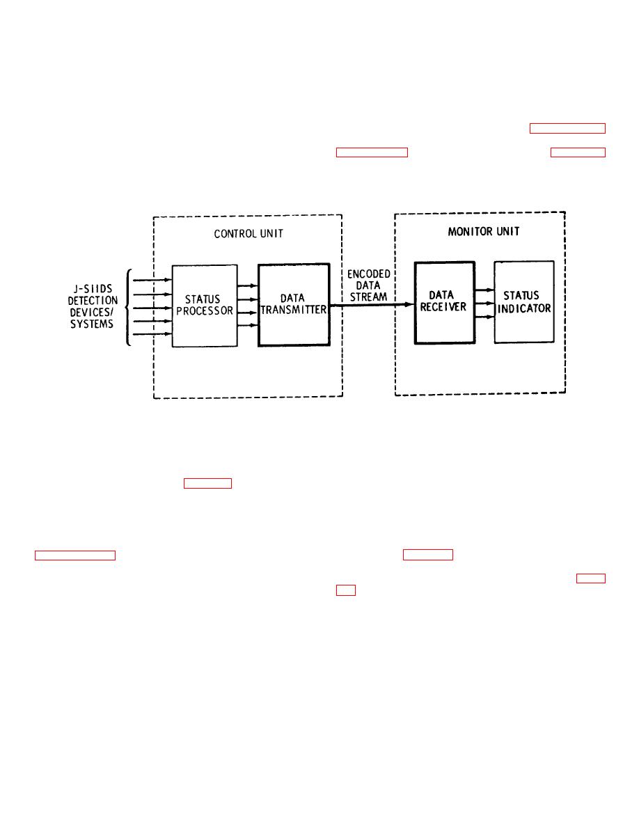
is a block diagram showing the relationship of the DTS-I
continual stream of encoded data words which are
to the overall J-SIID system, for reference.
generated in the transmitter of the system and which are
NOTE: DTS-I IS BOLDLY OUTLINED .
ME 6350-262-14/12/4-1
Figure 4-1. Overall block diagram, DTS-I and related components.
presented to the receiver of the system, by means of the
4-2. Functional Description
transmission line, as a serial stream of 12-bit words
b. Data Receiver. The data receiver receives
to the data transmitter. Four of the inputs (Instantaneous
the 12-bit word stream from the transmitter by means of
ALARM/NO ALARM, latched ALARM/NO ALARM,
the 600 ohm transmission line and from these words
ACCESS/SECURE, and AC POWER ON/AC POWER
decodes the current status at the status processor for
FAIL) are status inputs from the status processor. These
presentation to the associated status indicator in the
inputs represent the current status at the control unit.
monitor unit. Table 4-1 lists the pin connections at the
I/O (input/output) connector to the associated status
input to the receiver which correspond to the current
indicator and the function of each pin connection. Table
status conditions at the input to the status processor.
The other four inputs to the receiver are power and return
result depending on the status decoded by the receiver
inputs, and the resync initiation input. The status inputs
logic.
to the transmitter are encoded using a random bit
generator and modulo-2 adder logic (exclusive or), and
4-1
|
|
Privacy Statement - Press Release - Copyright Information. - Contact Us |