 |
|||
|
|
|||
|
Page Title:
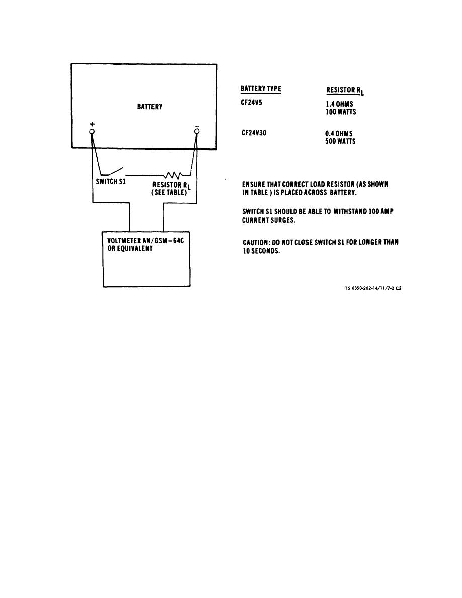
Figure 7-2. Battery Test Fixture |
|
||
| ||||||||||
|
|
 TM 5-6350-262-14/11
NAVELEX 0967-LP-466-9112
TO 31S9-4-39-1
Figure 7-2. Battery Test Fixture.
NOTE
e.
Recharging Batteries with Auxiliary Battery
Charger. If it is desirable to recharge the J-SIIDS
The value of resistance which must be
batteries utilizing a battery charger or power supply other
used to limit the current will decrease as
than that in the monitor cabinet the following proce-
the battery becomes charged. When
dures should be followed.
the battery is initially placed on charge
(1) The charging voltage must be maintained
use the highest value of resistance and
between 30 and 31 volts d.c.
verify that the current is below the
(2) The charging current into the batteries must
be limited below specified values either with an
maximum allowable. Once the battery
adjustable current limit in the power supply (this is the
has partially charged, this resistance
preferred method) or by placing a high wattage resistor
may be decreased in order to shorten
in series with the battery. The exact value of the resistor
the charging time. In no case should a
will vary depending upon the capacity of the battery, the
series resistor smaller than the lower
length of time that has elapsed since the batteries were
limit specified be used.
last charged, and the storage temperature.
The
maximum charging current for each battery and the
(3) As the battery charges, the current which it
approximate range of resistance which must be used if a
will accept will gradually decrease. When the charging
current limiting supply is not available are as follows:
cur- rent is reduced to approximately the following levels
Maximum charge
the battery is recharged and must be removed from the
Battery
current (amps)
Approximate resistance
charger.
ohms
watts
Battery
Current at full charge (amp)
CF24V5
0.800
5-15
10
CF24V5
0.075
CF24V30
5.000
1-3
100
CF24V30
0.200
NOTE
Some batteries may still accept 25%-
50% more current than specified, even
when fully
Change 2 7-6.2
|
|
Privacy Statement - Press Release - Copyright Information. - Contact Us |