 |
|||
|
|
|||
|
Page Title:
CHAPTER 4 FUNCTIONING OF EQUIPMENT |
|
||
| ||||||||||
|
|
 CHAPTER 4
FUNCTIONING OF EQUIPMENT
4-1. General
This chapter contains a circuit description of the
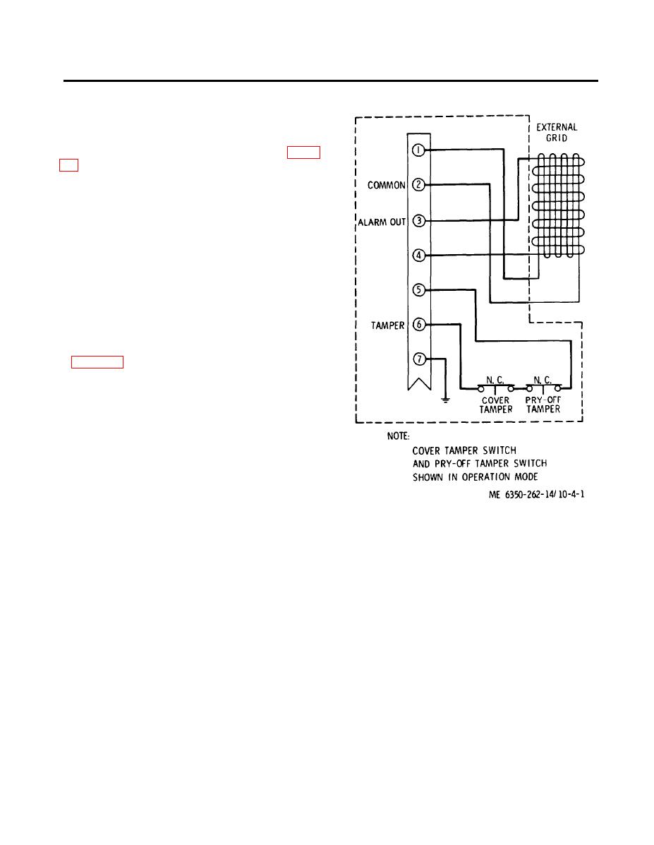
equipment operation. Explanations are keyed to the
grid wire sensor schematic diagram shown in figure
4-2. No-Alarm Condition
The normally installed, normally-operatinggrid wire
sensor provides 2 low impedance outputs (ALARM
and TAMPER) to the J-SIIDS Control Unit. The
ALARM output monitors the series-wired horizon-
tal grid and vertical grid network - e.g., alarm output
is provided at terminal 1 from the horizontally-wired
grid to terminal 2, and subsequently to terminal 3 to
the vertically-wired grid and back to terminal 4. The
low impedance TAMPER output monitors both the
Pryoff and Cover Tamper Switches. The TAMPER
output at terminal 5 is routed through the series-
wired tamper switches and back to terminal 6. Refer
to figure 4-1. One or more of the following conditions
will cause a change in the respective outputs, which
will be reflected into the input of the Control Unit
and subsequently will result in an alarm actuation.
4-3. Alarm Conditions.
a. If a wire is broken in either the horizontal or
vertical grid wire mesh, a high impedance output
change will be provided at the respective output
terminals.
b. If the cover, or junction box is moved from its
normal operating position, from 1/8 to 1/4 of an inch,
the output across terminals 5 and 6 will change to
Figure 4-1. Grid wire sensor electrical schematic diagram.
high impedance.
4-1
|
|
Privacy Statement - Press Release - Copyright Information. - Contact Us |