 |
|||
|
|
|||
|
Page Title:
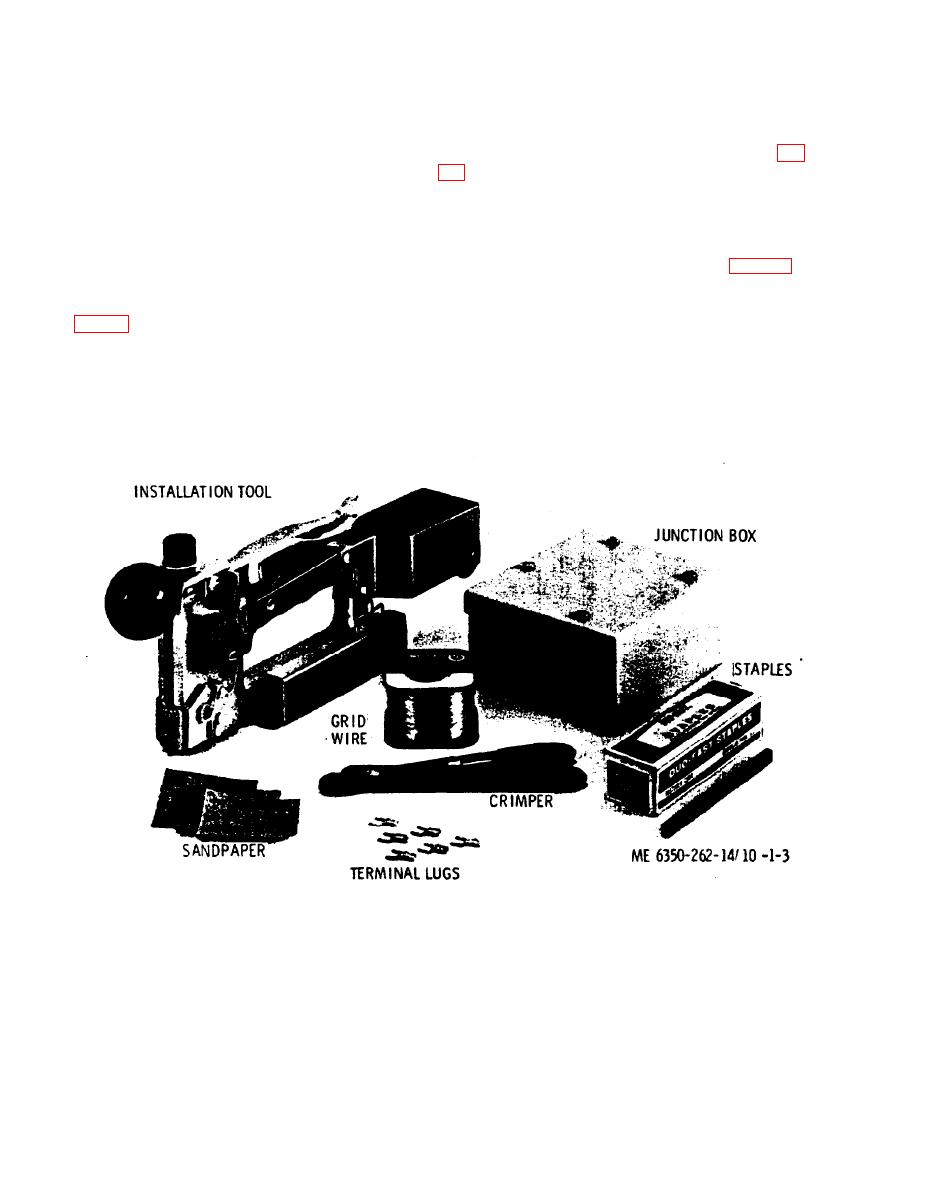
Figure 1-3. Grid wire kit components. |
|
||
| ||||||||||
|
|
 to prevent abrasion of the wire as it is pulled through
1-9. Description
the guide. The centering ensures that the wire will be
a. The grid wire sensor is a wire grid made up of
centered under the staple when each staple is set.
continuous electrical wires forming a pair of closed
The wire holder-dispenser attaching also provides a
electrical circuits and stapled to the barrier or to a
compartment for storing spare fasteners.
smooth foundation board which is then attached to
(2) Grid Wire Junction Box. The junction box (fig.
the barrier. The grid wire is protected by sandwich-
ing it between the barrier, or foundation board to
barrier strip, 2 SPDT pushbutton switches (cover
which it is attached, and finished interior panels that
and mounting-tamper switches), and associated
are placed over the wire grid and securely fastened to
wiring and switch mounting hardware.
the barrier or foundation board.
(3) Kit Components. The Grid Wire Sensor Kit
b. The Grid Wire Sensor will be supplied in the form
consists of the following components (see fin. 1-3):
(a) Grid wire installation tool
of a kit and shall consist of the following components:
(b) Grid wire
(1) Grid Wire Installation Gun. The installation
(c) Staples
gun (fig. 1-1) is comprised of a Duo-Fast Model 348-D
(d) Terminal crimping tool
Staple Gun modified to accommodate a grid wire
(e) Terminal lugs
holder dispenser. The grid wire is routed to the
(f) Sandpaper
proper position for stapling through a wire centering
(g) Operating instructions
guide. The centering guide contains a teflon bushing
Figure 1-3. Grid wire kit components.
1-11. Tabulated Data
1-10. Difference Between Models
a. Grid Wire Installation Gun.
This manual covers only the grid wire sensor
Weight (ready for operation) . . Less than 4 pounds.
DT-545( )/FSS-9(V). No known differences exist for
the model covered by this manual.
1-4
|
|
Privacy Statement - Press Release - Copyright Information. - Contact Us |
