 |
|||
|
|
|||
|
|
|||
| ||||||||||
|
|
 the other end of the cable check continuity between lead
NOTE
and conduit. Infinite indication is an open circuit.
Touchup paint Is recommended instead
d. Follow the procedure in step c above for the
of refinishing whenever practical.
remaining conductors in the cable.
(6) Check the equipment for applicable
7-7. Physical Test and Inspection
modification work orders (MWO).
a. General. This procedure is provided for use as
(7) Inspect overall unit for presence of dirt,
either the first step in troubleshooting, or use after
corrosion, moisture, and bits of wire and solder inside
repairs are completed and before the equipment is
the enclosure.
returned to the using organizations.
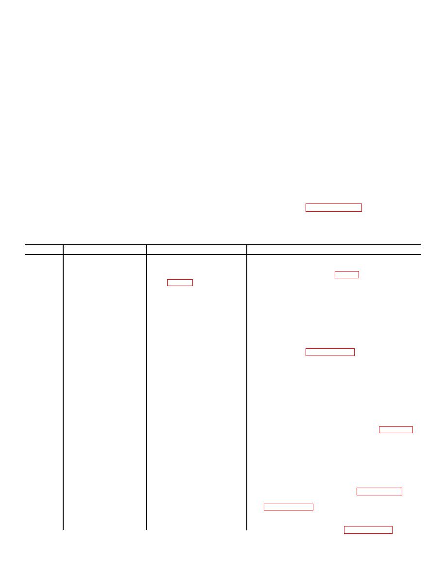
7-8. Symptom Analysis
b. Procedure.
Chart 7-1 lists identifiable symptoms to assist the
(1)
Inspect enclosure for evidence of
repairman in localizing potential faults.
physical damage.
NOTE
(2) Inspect terminal strips for cleanliness
and evidence of physical damage.
During performance of the symptom
(3) Check all resistors for evidence of
analysis when a pc board or a
discoloration due to overheating.
transducer Is replaced in either the
(4) Inspect all wiring and cabling for worn or
processor or the transceiver the RANGE
frayed insulation, and broken, or disconnected wires or
control must be reset and the tamper
cables.
switch circuit checked according to
(5) Inspect all metal surfaces, intended to
procedures In paragraph 2-18.
be painted, for condition of finish and legibility of panel
CHART 7-1. Troubleshooting Chart.
Step
Symptom
Procedure
Corrective Measures
1.
Constant alarm condition
a.
Check for 20 Vdc at
a. If voltage is below tolerance disconnect leads from
with all RANGE con-
terminals 7 and 8 of TB1
terminals 7 and 8 TB1 (fig. 1-1) and measure the
trols turned down to 1.
voltage level from the source.
b. If voltage is still below tolerance check intercon-
necting wiring.
c. If voltage is normal (202 Vdc) replace frequency
control transducer with a spare and check the in-
stallation in accordance with procedures in para-
graph 2-18.
d. If fault still exists replace processor pc board with a
spare and check the system in accordance with
procedures in paragraph 2-18.
b.
Check for 7 to 14 V rms
a. If the voltage is low or zero, disconnect the leads
at terminals 1 and 2 of
from the terminals 1 and 2 of TB2 and remeasure
TB2 in the processor.
from the voltage at these terminals
b. If the voltage is within tolerance check the inter-
connecting wires for shorts.
NOTE
All transmit transducers are connected in parallel
therefore interconnections between each unit will
have to be disconnected to isolate the cable failure.
Perform the cable checks procedure in Paragraph
7-6.
c. If interconnecting wires check correctly, temporarily
substitute a spare transmit transducer (white dot)
in each transceiver (one at a time) and recheck
voltage at terminals 1 and 2 of TB2 until the
faulty transducer has been located. When the
faulty transducer has been identified replace
transducer using procedures in paragraph 7-9.
Reset all RANGE controls using procedures in
d. If voltage is low prior to checking interconnecting
wires, replace the processor pc board with a spare
and perform procedures in paragraph 2-18.
7-3
|
|
Privacy Statement - Press Release - Copyright Information. - Contact Us |