 |
|||
|
|
|||
|
|
|||
| ||||||||||
|
|
 (13) Loosen and remove the four bolts, nuts
e.
Connecting Load Break Switch.
and washer in base fastening high voltage section to
(1) Identify and connect the conductors to the
trailer bed.
transformer, to their respective poles on the switch.
Connections on switch are at the bottom of each pole.
Make sure connecting lugs are clean and tight when
made.
(2) Replace the horizontally mounted insulator
barriers that were removed in subparagraph c. above.
These barriers are mounted around lone above and one
below) the switch primary connecting bars.
(3) Connect the leads from the lightning
arrestor to the primary connectors of switch. A lead from
each (of the three) lightning arresters goes up between
the conductors clamps to the bolt above. See figure 2-1.
Make sure connections are clean and tight.
(4) Check adjustment and alignment prior to
placing switch in service. See b. above.
(5) When switch is
declared serviceable,
primary connections may be made.
(6) Replace and secure rear panels.
(7) Close and secure front panels.
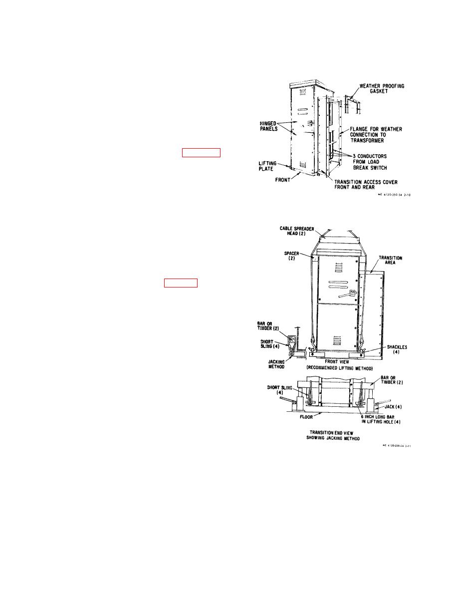
Figure 2-10. High voltage section.
2-15.
High Voltage Section Removal
a. Disconnect
High
Voltage
Section
from
Transformer.
(1) Clear trailer deck of all unnecessary
equipment.
(2) Loosen the 18 bolts securing the front
access cover of the transition area between transformer
and high voltage section, remove cover. (fig. 2-10 and 2-
11).
(3) Loosen and remove the three nuts
connecting the load break switch to the transformer.
Identify and mark each conductor for future hook lip.
(4) Replace and secure the front cover on the
transition area.
(5) Loosen and remove the three bolts
securing the lower front hinged panel, open panel.
(6) On the bottom left just behind heater is a
terminal board. Loosen and remove the two wires coming
out of the conduit connecting high voltage and low
voltage sections.
(7) Close and secure the lower front panel.
(8) Loosen and remove the six bolts and
washers securing the lower rear panel, remove panel.
(9) Loosen and disconnect the conduit in the
lower left bottom connecting the high voltage and low
voltage sections.
(10) Pull the two wires that were disconnected
from the heater terminal board free so that they will not
catch when moving high voltage section.
Figure 2-11. Lifting and jacking methods for high voltage
(11) Replace and secure lower rear panel.
section.
(12) Loosen and remove the 12 (6 each side)
b. Lifting High Voltage Section.
bolts, nuts and washers in the flange of the weatherproof
(I)
On the bottom at each corner are lifting
joint securing transition to transformer. Care must be
plates with holes. Attach at each corner a shackle to
taken not to damage gasket so that it may be reused.
2-10
|
|
Privacy Statement - Press Release - Copyright Information. - Contact Us |
