 |
|||
|
|
|||
|
|
|||
| ||||||||||
|
|
 two arc chute mounting bolts ( 2) at the top and the chute
so the blade will travel the full length without binding or
heavy scraping, and tighten the bolts. A dimension of 1-
1/16 inch should be maintained from the rear edge of the
arc chute to the front edge of the primary finger contact
support at all times, when moving or re-aligning the chute.
See figure 2-5. The auxiliary blade arc chute contacts (2,
fig. 2-91 inside the chute should be properly positioned to
latch the auxiliary blade when this dimension is
maintained. The auxiliary blade must be released by the
contacts when the primary blade has been opened to a
predetermined gap. With the operating springs blocked,
open the primary contacts and slowly move the primary
blade until the auxiliary blade is released. At the point of
release, the gap from the lower edge of the primary finger
(the bottom finger 2, fig. 2-7) to the primary blade stop
13, fig. 2-7) should be 4-7 /8 to 5-3 / 8 inches. If the gap
is not correct the vertical location of the chute must be
changed. For gaps greater than the above range the
chute must be lowered. For gaps that are less the chute
must be raised. To adjust the chute, remove the upper
and lower mounting bolts (2 and 10, fig. 2-5). Move
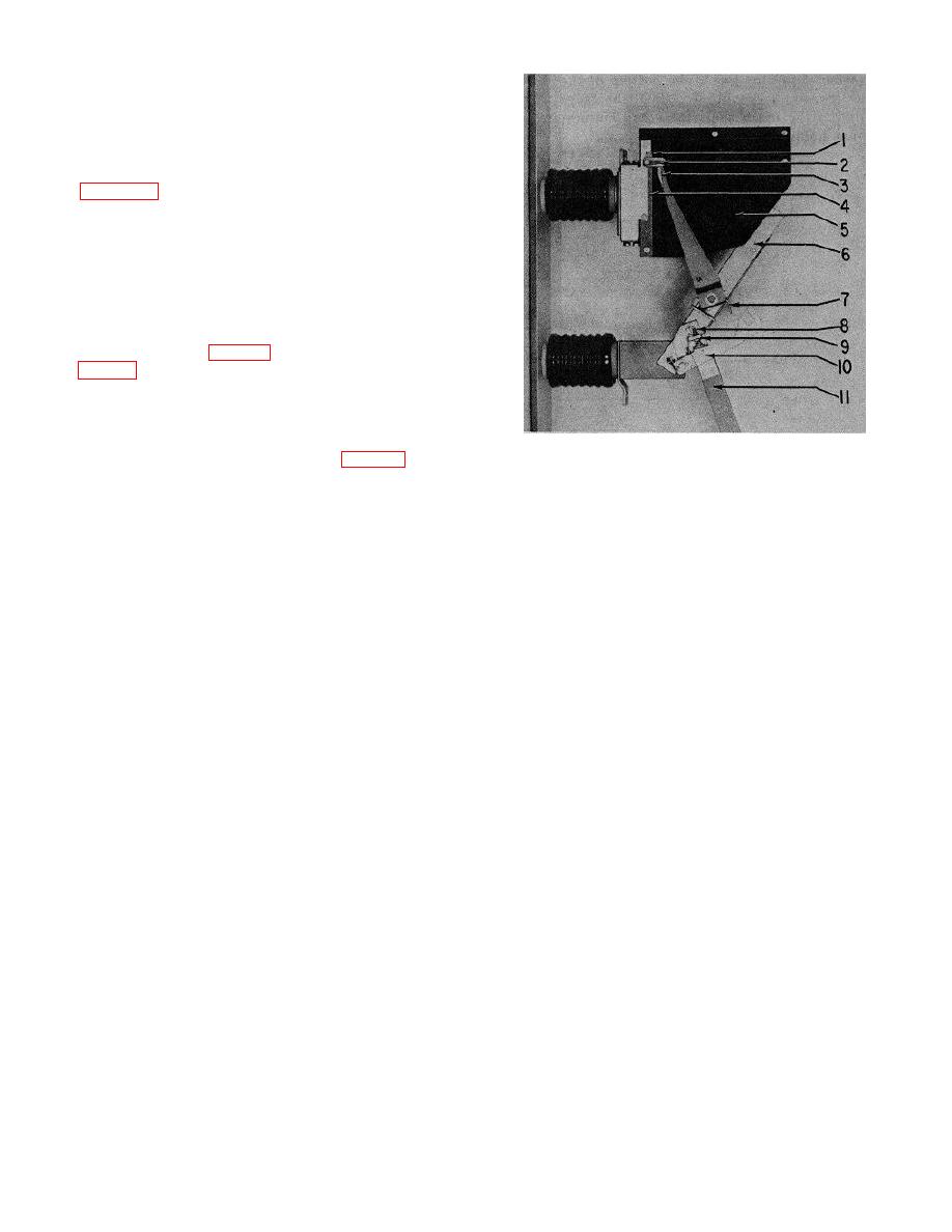
1. Blade stop block
shims (3, fig. 2-81 from the bottom to the top of the
2. Arc chute contacts
support to decrease the gap. To increase the gap move
3. Auxiliary blade
some of the top shims to the bottom support. When the
4. Spacer
release gap is properly set, check again the dimension
5. Arc chute side
from the back edge of the chute to the primary contact
6. Primary contact blade
finger support as directed above.
7. Auxiliary blade spring
8. Camming screw
9. Lock nut
10. Auxiliary blade release hook
11 Operating rod
Figure 2-9. Unit pole opening.
2-8
|
|
Privacy Statement - Press Release - Copyright Information. - Contact Us |
