 |
|||
|
|
|||
|
Page Title:
Figure 3-20. Crankcase cover (oil pan) and engine supports, Removal and installation. |
|
||
| ||||||||||
|
|
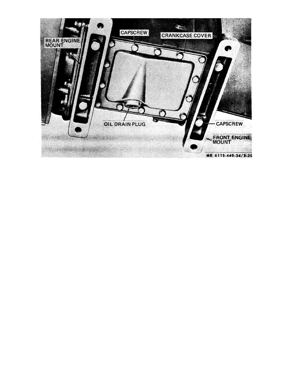 Figure 3-20. Crankcase cover (oil pan) and engine supports, Removal and installation.
3-22. Oil Pump
d. Inspection.
(1) Inspect the gears for cracked, chipped, or
a. General. The engine lubrication oil pump is
worn teeth.
submerged in the lubrication oil and force feeds the
oil to spray nozzles, which spray oil to the con-
(2) Inspect body for cracks.
necting rod bearings and other operating parts of
(3) Test the fit of the idler gear on the idler
gear shaft. The gear should turn freely but should
the engine.
have no perceptible wobble. Replace a defective
b. Removal
gear or shaft.
(1) Remove the gear cover (para 3-20).
(4) Measure the oil pump drive shaft diameter
(2) Remove crankcase cover and engine
and body bore. If the drive shaft is worn less than
supports (para 3-21).
0.4993 inch or if the pump body bore is more than
(3) Remove oil pump and pump drive gear
0.5015 inch, replace the drive shaft and pump
(fig. 3-21 ) as follows:
body.
.(a) Remove slotted pipe plug and oil pump
(5) Inspect the strainer screen for tears or
lockscrew.
enlarged openings and replace if defective.
(b) Remove locknut holding oil pump
e. Reassembly. Refer to figure 3-22 and
driving gear to shaft.
reassemble the oil pump in the reverse order of
(c) Use a soft brass rod or punch and drive
disassembly.
shaft through gear.
f. Installation.
(d) Withdraw oil pump toward center of
(1) Install the oil pump in the reverse
crankcase.
procedure of removal (fig. 3-21).
c. D i s a s s e m b l y . R e f e r t o f i g u r e 3 - 2 2 a n d
(2) Install the crankcase cover and engine
disassemble the oil pump in numerical sequence.
supports (para 3-21).
(3) Install the gear cover (para 3-20).
3-26
|
|
Privacy Statement - Press Release - Copyright Information. - Contact Us |
