 |
|||
|
|
|||
|
Page Title:
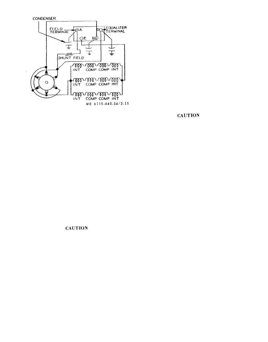
Figure 3-11. Internal wiring diagram. |
|
||
| ||||||||||
|
|
 strip of 5/0 sandpaper against the commutator to
polish the surface and remove burrs which might
have been left by the undercutting process. Stop the
lathe and set up a dial indicator gage to check the
accuracy of the finished commutator. The
maximum allowable eccentricity after polishing is
0.0001 inch total indicated run-out, and 0.0005
inch bar-to-bar.
f. Balancing t h e A r m a t u r e . A f t e r t h e c o m -
mutator has been refinished, check the armature
for proper balance, which should be within 20-
grain inches at each end. If a balance correction is
required, mill the retaining bands 0.032 inch deep
with a 0.25 inch diameter cutter. Mill until the
proper balance is obtained.
g. R e a s s e m b l y .
(1) Install new brush springs (4, fig. 3-10) to
brush holder assembly (1). It will be necessary to
wind each spring approximately 3/4 turn in order
to slide it on the spring support bar of the brush
holder (6).
Figure 3-11. Internal wiring diagram.
Do not wind spring more than necessary
e. Refinishing Commutator.
to engage into position as spring may
(1) Equipment required. To recondition the
take a permanent set
commutator within the tolerance limits, the work
(2) Install studs (5) to brush holder assembly
must be performed on a good lathe accurately set
(l).
up and adjusted. The commutator end of the ar-
(3) Slide the insulating tubes (9) into holes in
mature shaft should be supported on a bearing
support (10), and after coating both sides of in-
which can be used as a master by lapping out the
sulating plates (8) with insulating resin, assemble
inner race to obtain a slip fit to the armature shaft.
while still wet with brush holder assembly (1) to
The bearing should be supported by the turning
support (10).
center to support it in the tail stock of the lathe. The
(4) Slide an insulating washer (7) and washer
splined end of the armature should be driven by a
suitable collet or held on a center in the head stock
(3) over each stud and secure with nuts (2).
and driven with a lathe dog.
NOTE
(2) Making the cut. Adjust the lathe speed to
The brush holder assemblies must be
rotate the armature at approximately 600 rpm and,
p o s i t i o n e d so that brushes will be angled
toward direction of armature rotation.
using a sharp carboloy tool, take the lightest cut
possible with a fine feed. Remove only the amount
(5) Apply insulating resin over insulation and
o f material necessary to true the commutator
support (10), extending at least 0.06 inch from
surface. This may require making several cuts since
b r u s h holder insulators. Bake for one hour at
no more than 0.002 inch of material should be
150 F.
removed at any one time.
(6) Slide inner baffle disc (46, fig. 3-9) on
drive end of armature assembly (48), making sure
When new, the outside diameter of the
that hub of disc projects away from ball bearing
commutator i s 3 . 3 1 2 i n c h e s . W h e n
(53). Carefully press ball bearing (53) on drive end
repeated turning reduces this diameter
of armature until inner race of bearing in flush
to less than 3.187 inches the armature
against baffle disc. Install outer baffle disc (46) and
must be replaced.
replace retaining ring (43).
(3) Undercutting the mica. Using a reliable
( 7 ) Carefully press ball bearing (51) into
undercutting machine, undercut the mica between
bearing and brush holder support assembly (52),
the commutator bars 0.032 inch deep by 0.052
pressing only on outer race of bearing.
inch wide. Using a triangular scraper, remove all
( 8 ) Position retaining ring (49) over ball
sharp edges and burrs from the commutator bars.
bearing (51) and secure with screws (50). Lock
Remove all metal chips and mica particles from the
wire screws in pairs.
slots with a bristle brush and compressed air.
(9) Slide baffle disc (47) on commutator end
(4) P o l i s h i n g t h e c o m m u t a t o r . W i t h t h e a r -
of armature assembly (48). The hub of baffle disc
mature rotating at approximately 600 rpm, hold a
must project away from ball bearing (51).
3-16
|
|
Privacy Statement - Press Release - Copyright Information. - Contact Us |
