 |
|||
|
|
|||
|
Page Title:
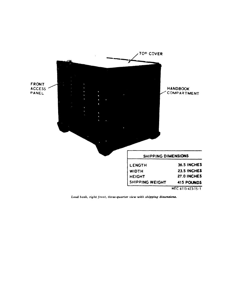
Figure 1. Load bank, right front, three-quarter view with shipping dimensions |
|
||
| ||||||||||
|
|
 TM 5-6115-423-15
Figure 1.
are connected to the terminal strip adjacent to
set up and controlled. Thus the capabilities
of the power generating equipment to perform
the control panel. Cables are not furnished
under these conditions can be tested and
with the equipment.
measured. The load bank is designed to test
(1) The load bank has a 3, 6 and two
the output characteristics of generating plants
9 kilowatt switches by which it can
rated 120/208 and 240/416 volts three phase
apply any fixed load in increments
4-wire; 240-volts three phase 3-wire; 120 or
of 3 up to 27 kilowatts. It can apply
240 volts single phase 2-wire. Tests can be
variable loads 0.5 to 3 kilowatts at
applied at frequencies between 50 and 1000
frequencies between 50 and 1000
cycles per second. Power cables connecting the
load bank and the equipment to be tested
cycles per second.
4
|
|
Privacy Statement - Press Release - Copyright Information. - Contact Us |
