 |
|||
|
|
|||
|
Page Title:
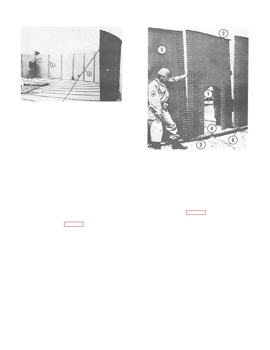
Figure 8-29. Bracing first stave and driving bolt heads into channels. |
|
||
| ||||||||||
|
|
 TM 5-5430-209-12
1. BOLT HEAD
2. STAVE JOINT CHANNEL
3. STAVE BRACE
ME 5430-209-12/8-29
Figure 8-29. Bracing first stave and driving bolt heads
into channels.
NOTE
Rope guy lines opposing each other may be
used as a substitute for the channel brace.
1.
SECOND AND THIRD RING STAVES
CAUTION
2.
LAST STAVE INSTALLED
3.
BOLT
Radii gaskets must be placed between chimes
4.
STRIP GASKET
and strip gaskets at the vertical seams, top
5.
NEXT-TO-LAST STAVE
and bottom of all staves, to insure a leakproof
6.
FIRST STAVE
ME 5430-209-12/8-30
joint.
CAUTION
Figure 8-30. Installing last stave.
All boltheads must be hammered squarely
into the stave joint channels to insure proper
(2) Set last stave (2) in position with the left seam
tightening of nuts.
outside the right seam of next-to-last stave (5) and its
(4) As staves are installed, hammer all bolt heads
right seam inside the left seam of first stave (6). Loosen
(1), except bolts with nuts, squarely into channels (2)
bottom chime nuts (5, fig. 8-26) of first stave (6, fig. 8-
from the inside the tank.
30).
e. Installing Last Stave.
(3) Lift first stave (6) slightly so the bottom chime of
(1) Push all bolts (3, fig. 3-30) flush with gasket (4)
last stave (2) slips into place. Use drift pins and aline
in the chime of the bottom to provide clearance for
the holes and bolts in staves (2, 5, and 6, ) following the
sliding in the last stave.
same procedure as in c (2) above
8-16
|
|
Privacy Statement - Press Release - Copyright Information. - Contact Us |